User Manual
Page 3
Contents Notices...v Safety information vi About this guide vii P5G41-M LX specifications summary viii Chapter 1: Product introduction 1.1 Before you proceed 1-1 1.2 Motherboard overview 1-2 1.2.1 Motherboard layout 1-2 1.2.2 Layout contents 1-2 1.3 Central Processing Unit (CPU 1-3 1.4 System memory 1-3 ... support 1-16 1.8.1 Installing an operating system 1-16 1.8.2 Support DVD information 1-16 Chapter 2: BIOS information 2.1 Managing and updating your BIOS 2-1 2.1.1 ASUS Update utility 2-1 2.1.2 ASUS EZ Flash 2 2-2 2.1.3 ASUS CrashFree BIOS 2-3 2.2 BIOS setup program 2-3 iii
Contents Notices...v Safety information vi About this guide vii P5G41-M LX specifications summary viii Chapter 1: Product introduction 1.1 Before you proceed 1-1 1.2 Motherboard overview 1-2 1.2.1 Motherboard layout 1-2 1.2.2 Layout contents 1-2 1.3 Central Processing Unit (CPU 1-3 1.4 System memory 1-3 ... support 1-16 1.8.1 Installing an operating system 1-16 1.8.2 Support DVD information 1-16 Chapter 2: BIOS information 2.1 Managing and updating your BIOS 2-1 2.1.1 ASUS Update utility 2-1 2.1.2 ASUS EZ Flash 2 2-2 2.1.3 ASUS CrashFree BIOS 2-3 2.2 BIOS setup program 2-3 iii
User Manual
Page 8
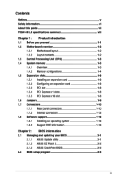
... or more, Windows® 32-bit operating system may only recognize less than 3GB. Supports RGB with max. P5G41-M LX specifications summary CPU Chipset Front Side Bus Memory Graphics Expansion slots Storage LAN Audio USB ASUS special features LGA775 socket for Intel® Core™2 Quad / Core™2 Extreme / Core™2 Duo / Pentium...
... or more, Windows® 32-bit operating system may only recognize less than 3GB. Supports RGB with max. P5G41-M LX specifications summary CPU Chipset Front Side Bus Memory Graphics Expansion slots Storage LAN Audio USB ASUS special features LGA775 socket for Intel® Core™2 Quad / Core™2 Extreme / Core™2 Duo / Pentium...
User Manual
Page 9
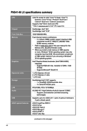
ix P5G41-M LX specifications summary Back panel I/O ports Internal I/O connectors BIOS features Support DVD contents Accessories Form factor 1 x PS/2 keyboard port 1 x PS/2 mouse port 1 x COM port 1 x VGA port 1 x ...-pin EATX power connector 1 x 4-pin ATX 12V power connector 8Mb Flash ROM, AMI BIOS, PnP, DMI 2.0, WfM 2.0, ACPI v2.0a, SM BIOS v2.5 Drivers ASUS PC Probe II ASUS LiveUpdate Utility Anti-virus software (OEM version) 2 x Serial ATA cables 1 x UltraDMA 100/66 cable 1 x I/O shield User Manual MicroATX form factor: 9.6 in x 7.2 in (24...
ix P5G41-M LX specifications summary Back panel I/O ports Internal I/O connectors BIOS features Support DVD contents Accessories Form factor 1 x PS/2 keyboard port 1 x PS/2 mouse port 1 x COM port 1 x VGA port 1 x ...-pin EATX power connector 1 x 4-pin ATX 12V power connector 8Mb Flash ROM, AMI BIOS, PnP, DMI 2.0, WfM 2.0, ACPI v2.0a, SM BIOS v2.5 Drivers ASUS PC Probe II ASUS LiveUpdate Utility Anti-virus software (OEM version) 2 x Serial ATA cables 1 x UltraDMA 100/66 cable 1 x I/O shield User Manual MicroATX form factor: 9.6 in x 7.2 in (24...
User Manual
Page 10
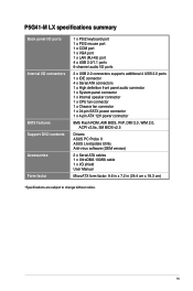
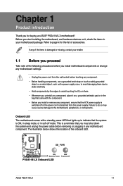
...supply is switched off mode. If any of the items is a reminder that lights up to page ix for buying an ASUS® P5G41-M LX motherboard! Before you uninstall any component, place it on it, check the items in the bag that came with a standby... by the edges to the motherboard, peripherals, or components. The illustration below shows the location of accessories. SB_PWR P5G41-M LX ON OFF Standby Power Powered Off P5G41-M LX Onboard LED ASUS P5G41-M LX 1-1 Chapter 1 Product introduction Thank you must shut down the system and unplug the power cable before touching any ...
...supply is switched off mode. If any of the items is a reminder that lights up to page ix for buying an ASUS® P5G41-M LX motherboard! Before you uninstall any component, place it on it, check the items in the bag that came with a standby... by the edges to the motherboard, peripherals, or components. The illustration below shows the location of accessories. SB_PWR P5G41-M LX ON OFF Standby Power Powered Off P5G41-M LX Onboard LED ASUS P5G41-M LX 1-1 Chapter 1 Product introduction Thank you must shut down the system and unplug the power cable before touching any ...

User Manual
Page 12
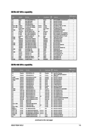
...removal, or misplacement/loss/incorrect removal of the DDR2 DIMM sockets: DIMM_A1 DIMM_B1 Channel Channel A Channel B P5G41-M LX P5G41-M LX 240-pin DDR2 DIMM sockets Sockets DIMM_A1 DIMM_B1 ASUS P5G41-M LX 1-3 Contact your retailer immediately if the PnP cap is on the LGA775 socket. • The product ...warranty does not cover damage to the PnP cap/socket contacts/motherboard components. ASUS will shoulder the cost of ...
...removal, or misplacement/loss/incorrect removal of the DDR2 DIMM sockets: DIMM_A1 DIMM_B1 Channel Channel A Channel B P5G41-M LX P5G41-M LX 240-pin DDR2 DIMM sockets Sockets DIMM_A1 DIMM_B1 ASUS P5G41-M LX 1-3 Contact your retailer immediately if the PnP cap is on the LGA775 socket. • The product ...warranty does not cover damage to the PnP cap/socket contacts/motherboard components. ASUS will shoulder the cost of ...
User Manual
Page 14
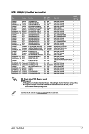
...-Sink Package DS Heat-Sink Package SS HY5PS12821CFP-S5 DS HY5PS12821CFPS5 • • • • • • • • • (continued on the next page) ASUS P5G41-M LX 1-5 DDR2-667 MHz capability Size Vendor Part No. CL 1G 1G 2G 2G 2G(2 x 1GB) 4G(2 x 2GB) 1G 512MB 4G 1G 1G 1G 512MB 512MB...
...-Sink Package DS Heat-Sink Package SS HY5PS12821CFP-S5 DS HY5PS12821CFPS5 • • • • • • • • • (continued on the next page) ASUS P5G41-M LX 1-5 DDR2-667 MHz capability Size Vendor Part No. CL 1G 1G 2G 2G 2G(2 x 1GB) 4G(2 x 2GB) 1G 512MB 4G 1G 1G 1G 512MB 512MB...
User Manual
Page 16
Double - Visit the ASUS website at www.asus.com for the latest QVL. ASUS P5G41-M LX 1-7 support A* B* Heat-Sink Package •• Heat-Sink Package •• Heat-Sink Package •• Heat-Sink Package •• 9CE12 D9JKH •• ...
Double - Visit the ASUS website at www.asus.com for the latest QVL. ASUS P5G41-M LX 1-7 support A* B* Heat-Sink Package •• Heat-Sink Package •• Heat-Sink Package •• Heat-Sink Package •• 9CE12 D9JKH •• ...
User Manual
Page 18
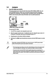
... cap will cause system boot failure! • If the steps above do not need to clear the RTC when the system hangs due to pins 2-3. ASUS P5G41-M LX 1-9 Turn OFF the computer and unplug the power cord. 2. Except when clearing the RTC RAM, never remove the cap on pins 2-3 for about 5-10 seconds...
... cap will cause system boot failure! • If the steps above do not need to clear the RTC when the system hangs due to pins 2-3. ASUS P5G41-M LX 1-9 Turn OFF the computer and unplug the power cord. 2. Except when clearing the RTC RAM, never remove the cap on pins 2-3 for about 5-10 seconds...
User Manual
Page 20
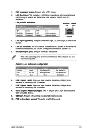
... Network (LAN) through a network hub. Line In port (light blue). LAN (RJ-45) port. This port connects a microphone. This port is for connecting USB 2.0 devices. 8. ASUS P5G41-M LX 1-11 These two 4-pin Universal Serial Bus (USB) ports are available for a PS/2 keyboard. This 15-pin port is for pointing devices or other audio...
... Network (LAN) through a network hub. Line In port (light blue). LAN (RJ-45) port. This port connects a microphone. This port is for connecting USB 2.0 devices. 8. ASUS P5G41-M LX 1-11 These two 4-pin Universal Serial Bus (USB) ports are available for a PS/2 keyboard. This 15-pin port is for pointing devices or other audio...
User Manual
Page 21
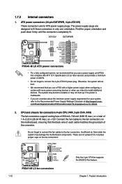
... the Recommended Power Supply Wattage Calculator at +12V. P5G41-M LX CPU_FAN GND CPU FAN PWR CPU FAN IN CPU FAN PWM CHA_FAN GND +12V Rotation Only the 4-pin CPU fan supports the ASUS Q-Fan feature. The power supply plugs are not... the fan cables to connect the 4-pin ATX12V power plug. ATX12V EATXPWR +12V DC +12V DC P5G41-M LX GND GND +3 Volts +12 Volts +12 Volts +5V Standby Power OK PIN 1 GND +5 Volts GND +5 Volts GND +3...each cable matches the ground pin of 1 A~2.22 A (26.64 W max.) at http://support.asus. P5G41-M LX fan connectors 1-12 Chapter 1: Product introduction
... the Recommended Power Supply Wattage Calculator at +12V. P5G41-M LX CPU_FAN GND CPU FAN PWR CPU FAN IN CPU FAN PWM CHA_FAN GND +12V Rotation Only the 4-pin CPU fan supports the ASUS Q-Fan feature. The power supply plugs are not... the fan cables to connect the 4-pin ATX12V power plug. ATX12V EATXPWR +12V DC +12V DC P5G41-M LX GND GND +3 Volts +12 Volts +12 Volts +5V Standby Power OK PIN 1 GND +5 Volts GND +5 Volts GND +3...each cable matches the ground pin of 1 A~2.22 A (26.64 W max.) at http://support.asus. P5G41-M LX fan connectors 1-12 Chapter 1: Product introduction
User Manual
Page 22
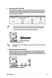
... Two devices Drive jumper setting Cable-Select or Master Cable-Select Master Slave Mode of the following modes to PIN 1. PRI_IDE P5G41-M LX PIN1 NOTE:Orient the red markings on the Ultra DMA cable connector. The data transfer rate of the Serial ATA 3Gb/s is...GND RSATA_TXN3 RSATA_TXP3 GND SATA1 SATA3 SATA4 GND RSATA_TXP4 RSATA_TXN4 GND RSATA_RXP4 RSATA_RXN4 GND SATA2 GND RSATA_TXP2 RSATA_TXN2 GND RSATA_RXP2 RSATA_RXN2 GND P5G41-M LX SATA connectors ASUS P5G41-M LX 1-13 Serial ATA connectors (7-pin SATA1-4) These connectors are three connectors on each Ultra DMA 100/66 signal cable: ...
... Two devices Drive jumper setting Cable-Select or Master Cable-Select Master Slave Mode of the following modes to PIN 1. PRI_IDE P5G41-M LX PIN1 NOTE:Orient the red markings on the Ultra DMA cable connector. The data transfer rate of the Serial ATA 3Gb/s is...GND RSATA_TXN3 RSATA_TXP3 GND SATA1 SATA3 SATA4 GND RSATA_TXP4 RSATA_TXN4 GND RSATA_RXP4 RSATA_RXN4 GND SATA2 GND RSATA_TXP2 RSATA_TXN2 GND RSATA_RXP2 RSATA_RXN2 GND P5G41-M LX SATA connectors ASUS P5G41-M LX 1-13 Serial ATA connectors (7-pin SATA1-4) These connectors are three connectors on each Ultra DMA 100/66 signal cable: ...
User Manual
Page 24
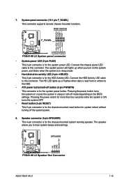
... power LED lights up or flashes when data is read from or written to this connector. SPEAKER P5G41-M LX PIN 1 P5G41-M LX Speaker Out Connector +5V GND GND Speaker Out ASUS P5G41-M LX 1-15 PLED PWR BTN F_PANEL PIN 1 P5G41-M LX +HDLED RESET P5G41-M LX System panel connector • System power LED (2-pin PLED) This 2-pin connector is for the chassis...
... power LED lights up or flashes when data is read from or written to this connector. SPEAKER P5G41-M LX PIN 1 P5G41-M LX Speaker Out Connector +5V GND GND Speaker Out ASUS P5G41-M LX 1-15 PLED PWR BTN F_PANEL PIN 1 P5G41-M LX +HDLED RESET P5G41-M LX System panel connector • System power LED (2-pin PLED) This 2-pin connector is for the chassis...
User Manual
Page 26
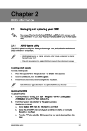
... from the Internet, then click Next. Follow the onscreen instructions to launch the ASUS Update utility. 2. ASUS P5G41-M LX 2-1 Copy the original motherboard BIOS using this utility. The Drivers menu appears. 2. b. Installing ASUS Update To install ASUS Update: 1. Click the Utilities tab, then click ASUS Update. 3. c. Quit all Windows® applications before you update the BIOS using...
... from the Internet, then click Next. Follow the onscreen instructions to launch the ASUS Update utility. 2. ASUS P5G41-M LX 2-1 Copy the original motherboard BIOS using this utility. The Drivers menu appears. 2. b. Installing ASUS Update To install ASUS Update: 1. Click the Utilities tab, then click ASUS Update. 3. c. Quit all Windows® applications before you update the BIOS using...
User Manual
Page 28
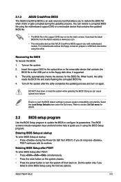
...BIOS default settings to restore the BIOS file when it fails or gets corrupted during the Power-On Self Test (POST). 2.1.3 ASUS CrashFree BIOS The ASUS CrashFree BIOS is an auto recovery tool that allows you do not press , POST continues with motherboard models. Download the latest BIOS... startup To enter BIOS Setup at www.asus.com. • The removable devices that contains the BIOS file to the USB port or to the optical drive or the removable device that ASUS CrashFree BIOS support vary with its parameters. If you to ensure system compatibility and stability. ASUS P5G41-M LX 2-3
...BIOS default settings to restore the BIOS file when it fails or gets corrupted during the Power-On Self Test (POST). 2.1.3 ASUS CrashFree BIOS The ASUS CrashFree BIOS is an auto recovery tool that allows you do not press , POST continues with motherboard models. Download the latest BIOS... startup To enter BIOS Setup at www.asus.com. • The removable devices that contains the BIOS file to the USB port or to the optical drive or the removable device that ASUS CrashFree BIOS support vary with its parameters. If you to ensure system compatibility and stability. ASUS P5G41-M LX 2-3
User Manual
Page 30
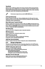
... or disables data multi-sectors transfers. When set or change the configurations for detecting ATA/ATAPI devices. Configuration options: [0] [5] [10] [15] [20] [25] [30] [35] ASUS P5G41-M LX 2-5 Setting to the device occurs multiple sectors at a time. Configuration options: [Auto] [0] [1] [2] [3] [4] DMA Mode [Auto] Selects the DMA mode. Select ARMD (ATAPI Removable Media Device...
... or disables data multi-sectors transfers. When set or change the configurations for detecting ATA/ATAPI devices. Configuration options: [0] [5] [10] [15] [20] [25] [30] [35] ASUS P5G41-M LX 2-5 Setting to the device occurs multiple sectors at a time. Configuration options: [Auto] [0] [1] [2] [3] [4] DMA Mode [Auto] Selects the DMA mode. Select ARMD (ATAPI Removable Media Device...
User Manual
Page 32
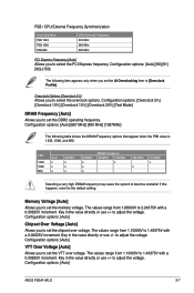
...] [91] [92]~[150] The following table shows the DRAM Frequency options that appear when the FSB value is 1333, 1066, and 800. Configuration options: [Auto] ASUS P5G41-M LX 2-7 Overclock Options [Overclock 5%] Allows you to select the overclock options.
...] [91] [92]~[150] The following table shows the DRAM Frequency options that appear when the FSB value is 1333, 1066, and 800. Configuration options: [Auto] ASUS P5G41-M LX 2-7 Overclock Options [Overclock 5%] Allows you to select the overclock options.
User Manual
Page 34
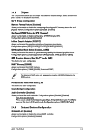
...] Front Panel Type [HD Audio] Allows you to select the DVMT memory. If High Definition Audio Front Panel used by SPD. Configuration options: [Enabled] [Disabled] ASUS P5G41-M LX 2-9 Protect Audio Video Path Mode [Lite] This item is not user- DVMT Memory [256MB] Allows you to select the front panel support type. Configuration options...
...] Front Panel Type [HD Audio] Allows you to select the DVMT memory. If High Definition Audio Front Panel used by SPD. Configuration options: [Enabled] [Disabled] ASUS P5G41-M LX 2-9 Protect Audio Video Path Mode [Lite] This item is not user- DVMT Memory [256MB] Allows you to select the front panel support type. Configuration options...
User Manual
Page 36
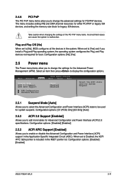
... (APM). Configuration options: [No] [Yes] 2.5 Power menu The Power menu items allow you to change the settings for legacy ISA devices. Configuration options: [Disabled] [Enabled] ASUS P5G41-M LX 2-11 Main Advanced Power BIOS SETUP UTILITY Boot Tools Exit Suspend Mode [Auto] ACPI 2.0 Support [Enabled] ACPI APIC Support [Enabled] APM Configuration Hardware Monitor Select...
... (APM). Configuration options: [No] [Yes] 2.5 Power menu The Power menu items allow you to change the settings for legacy ISA devices. Configuration options: [Disabled] [Enabled] ASUS P5G41-M LX 2-11 Main Advanced Power BIOS SETUP UTILITY Boot Tools Exit Suspend Mode [Auto] ACPI 2.0 Support [Enabled] ACPI APIC Support [Enabled] APM Configuration Hardware Monitor Select...
User Manual
Page 38
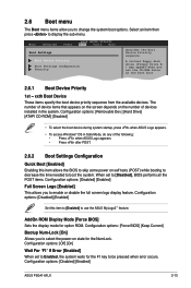
...[Enabled] Full Screen Logo [Enabled] This allows you set to Enabled, the system waits for option ROM. Configuration options: [Disabled] [Enabled] ASUS P5G41-M LX 2-13 When set the CD-ROM drive as the first boot device. 2.6.1 Boot Device Priority 1st ~ xxth Boot Device These items specify the ... options: [Disabled] [Enabled] Set this item allows the BIOS to skip some power on the number of the following: • Press when ASUS Logo appears. • Press after POST. 2.6.2 Boot Settings Configuration Quick Boot [Enabled] Enabling this item to [Enabled] to display the sub...
...[Enabled] Full Screen Logo [Enabled] This allows you set to Enabled, the system waits for option ROM. Configuration options: [Disabled] [Enabled] ASUS P5G41-M LX 2-13 When set the CD-ROM drive as the first boot device. 2.6.1 Boot Device Priority 1st ~ xxth Boot Device These items specify the ... options: [Disabled] [Enabled] Set this item allows the BIOS to skip some power on the number of the following: • Press when ASUS Logo appears. • Press after POST. 2.6.2 Boot Settings Configuration Quick Boot [Enabled] Enabling this item to [Enabled] to display the sub...
User Manual
Page 40
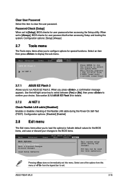
...when accessing the Setup utility. When you to clear the user password. Select+FFEEFFEo-11Sn11Sn0Ct0CeeorSSCGSEf eeheaxtSSGGSEhllanvieeoeaxeeeneetllnviccgroeeteettteaapccorlntttaaioSIOdSlnnctpHSIudsreteEctbHemilxfre-eEreopioemslxnntmecpinrtteheisn ASUS P5G41-M LX 2-15 Password Check [Setup] When set to exit this item to run the utility to confirm...FAT 12/16/32 (r/w) 2.NTFS (read only) 3.CD-DISC (read only) 2.7.1 ASUS EZ Flash 2 Allows you press , a confirmation message appears. See section 2.1.2 ASUS EZ Flash 2 for details. 2.7.2 AI NET 2 Check Realtek LAN cable [Disabled] Enables...
...when accessing the Setup utility. When you to clear the user password. Select+FFEEFFEo-11Sn11Sn0Ct0CeeorSSCGSEf eeheaxtSSGGSEhllanvieeoeaxeeeneetllnviccgroeeteettteaapccorlntttaaioSIOdSlnnctpHSIudsreteEctbHemilxfre-eEreopioemslxnntmecpinrtteheisn ASUS P5G41-M LX 2-15 Password Check [Setup] When set to exit this item to run the utility to confirm...FAT 12/16/32 (r/w) 2.NTFS (read only) 3.CD-DISC (read only) 2.7.1 ASUS EZ Flash 2 Allows you press , a confirmation message appears. See section 2.1.2 ASUS EZ Flash 2 for details. 2.7.2 AI NET 2 Check Realtek LAN cable [Disabled] Enables...


