
Motherboard DIY Troubleshooting Guide
Page 3
Features Contents Notices v Safety information vi About this guide vii ASUS contact information viii P4PE BP specifications summary ix Chapter 1: Product introduction 1.1 Welcome 1-2 1.2 Package contents 1-2 1.3 Special features 1-3 1.4 Motherboard components 1-4... 1-15 1.11 Jumpers 1-16 1.12 Connectors 1-18 Chapter 2: BIOS information 2.1 Managing and updating your BIOS 2-2 2.1.1 Using ASUS EZ Flash to update the BIOS 2-2 2.1.2 Using AFLASH to update the BIOS 2-4 2.1.3 CrashFree BIOS 2 feature 2-7 2.2 BIOS Setup program 2-8 2.2.1 BIOS menu bar 2-8 2.2.2 Legend bar 2-9 iii
Features Contents Notices v Safety information vi About this guide vii ASUS contact information viii P4PE BP specifications summary ix Chapter 1: Product introduction 1.1 Welcome 1-2 1.2 Package contents 1-2 1.3 Special features 1-3 1.4 Motherboard components 1-4... 1-15 1.11 Jumpers 1-16 1.12 Connectors 1-18 Chapter 2: BIOS information 2.1 Managing and updating your BIOS 2-2 2.1.1 Using ASUS EZ Flash to update the BIOS 2-2 2.1.2 Using AFLASH to update the BIOS 2-4 2.1.3 CrashFree BIOS 2 feature 2-7 2.2 BIOS Setup program 2-8 2.2.1 BIOS menu bar 2-8 2.2.2 Legend bar 2-9 iii

Motherboard DIY Troubleshooting Guide
Page 9
P4PE BP specifications summary CPU Chipset Front Side Bus (FSB) Memory Expansion slots IDE Audio (optional) LAN (optional) Special features Rear panel I/O Socket 478 for Intel® ... AD1980 6-channel audio CODEC BROADCOM® BCM4401 Fast Ethernet controller ASUS JumperFree™ mode ASUS EZ Plug™ ASUS MyLogo2 ASUS Q-Fan ASUS EZ Flash ASUS Instant Music ASUS POST Reporter Power Loss Restart SFS (Stepless Frequency Selection) Adjustable CPU VCORE, memory, and AGP voltages Multi-language BIOS 1 x Parallel port 2 x Serial ports 1 x PS/2 keyboard port 1 x PS/2 mouse port...
P4PE BP specifications summary CPU Chipset Front Side Bus (FSB) Memory Expansion slots IDE Audio (optional) LAN (optional) Special features Rear panel I/O Socket 478 for Intel® ... AD1980 6-channel audio CODEC BROADCOM® BCM4401 Fast Ethernet controller ASUS JumperFree™ mode ASUS EZ Plug™ ASUS MyLogo2 ASUS Q-Fan ASUS EZ Flash ASUS Instant Music ASUS POST Reporter Power Loss Restart SFS (Stepless Frequency Selection) Adjustable CPU VCORE, memory, and AGP voltages Multi-language BIOS 1 x Parallel port 2 x Serial ports 1 x PS/2 keyboard port 1 x PS/2 mouse port...

Motherboard DIY Troubleshooting Guide
Page 10
P4PE BP specifications summary Internal I/O BIOS features Industry standard Manageability Form Factor Support CD contents 1 x USB 2.0/1.1 connector for 2 additional USB ports CPU/Power/Chassis fan connectors 20-pin/4-pin ATX ...) S/PDIF Out connector (optional) CD/AUX/Modem audio connectors (optional) Front panel audio connector (optional) 4Mb Flash ROM, Award BIOS, TCAV, PnP, DMI2.0, WfM2.0, SM BIOS2.3, CrashFree BIOS, Multi-language BIOS, ASUS EZ Flash, ASUS MyLogo2, ASUS Instant Music PCI 2.2, USB 2.0 WfM 2.0. x DMI 2.0, WOL/WOR by PME, chassis intrusion, SMBus ATX form factor: 12 in x ...
P4PE BP specifications summary Internal I/O BIOS features Industry standard Manageability Form Factor Support CD contents 1 x USB 2.0/1.1 connector for 2 additional USB ports CPU/Power/Chassis fan connectors 20-pin/4-pin ATX ...) S/PDIF Out connector (optional) CD/AUX/Modem audio connectors (optional) Front panel audio connector (optional) 4Mb Flash ROM, Award BIOS, TCAV, PnP, DMI2.0, WfM2.0, SM BIOS2.3, CrashFree BIOS, Multi-language BIOS, ASUS EZ Flash, ASUS MyLogo2, ASUS Instant Music PCI 2.2, USB 2.0 WfM 2.0. x DMI 2.0, WOL/WOR by PME, chassis intrusion, SMBus ATX form factor: 12 in x ...
Motherboard DIY Troubleshooting Guide
Page 16
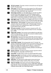
...a multi-mode parallel port, two standard compatible UARTs, a Standard Infrared (SIR), and a Flash ROM interface. 1-6 Chapter 1: Product introduction This ASUS patented auxilliary power connector is a subsystem that supports AGP 2.0 specification including 4X Fast Write protocol. The power supply must have an ATX +12V ...power supply. This 4Mb firmware contains the programmable BIOS program. 12 Standby power LED. This Low Pin Count (LPC) interface provides the commonly used if you don't have at 333/...
...a multi-mode parallel port, two standard compatible UARTs, a Standard Infrared (SIR), and a Flash ROM interface. 1-6 Chapter 1: Product introduction This ASUS patented auxilliary power connector is a subsystem that supports AGP 2.0 specification including 4X Fast Write protocol. The power supply must have an ATX +12V ...power supply. This 4Mb firmware contains the programmable BIOS program. 12 Standby power LED. This Low Pin Count (LPC) interface provides the commonly used if you don't have at 333/...
Motherboard DIY Troubleshooting Guide
Page 21
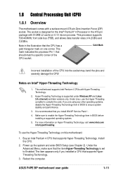
... Technology is designed for the Intel® Pentium® 4 Processor in BIOS before installing a supported operating system. 5. If you installed a CPU that supports Hyper-Threading Technology. Install the CPU. 2. Reboot the computer. ASUS P4PE BP motherboard user guide 1-11 The socket is supported under Windows XP and Linux.... Notes on Hyper-Threading Technology, visit www.intel.com/ info/hyperthreading. Power up the system and enter BIOS Setup (see Chapter 2). The item appears only if you are using any other operating systems, disable the Hyper-Threading Techonology item in...
... Technology is designed for the Intel® Pentium® 4 Processor in BIOS before installing a supported operating system. 5. If you installed a CPU that supports Hyper-Threading Technology. Install the CPU. 2. Reboot the computer. ASUS P4PE BP motherboard user guide 1-11 The socket is supported under Windows XP and Linux.... Notes on Hyper-Threading Technology, visit www.intel.com/ info/hyperthreading. Power up the system and enter BIOS Setup (see Chapter 2). The item appears only if you are using any other operating systems, disable the Hyper-Threading Techonology item in...

Motherboard DIY Troubleshooting Guide
Page 24
.... 1-14 Chapter 1: Product introduction Single-sided DIMM DS - Double-sided x16 DDR DIMMs are not supported on the system and change the necessary BIOS settings, if any DDR DIMMs with the chassis. Double-sided DIMM DDR DIMM2 (Rows 2&3) DS SS DDR DIMM3 (Rows 3&2) None SS 1.... an IRQ to the tables below. 4. NOTE: The AGP slot supports only 1.5V AGP cards. 2. Install the drivers and/or software applications for BIOS information. 3. See Chapter 2 for the expansion card according to install DDR DIMMs. Otherwise, the system may not boot up. Turn on this motherboard....
.... 1-14 Chapter 1: Product introduction Single-sided DIMM DS - Double-sided x16 DDR DIMMs are not supported on the system and change the necessary BIOS settings, if any DDR DIMMs with the chassis. Double-sided DIMM DDR DIMM2 (Rows 2&3) DS SS DDR DIMM3 (Rows 3&2) None SS 1.... an IRQ to the tables below. 4. NOTE: The AGP slot supports only 1.5V AGP cards. 2. Install the drivers and/or software applications for BIOS information. 3. See Chapter 2 for the expansion card according to install DDR DIMMs. Otherwise, the system may not boot up. Turn on this motherboard....

Motherboard DIY Troubleshooting Guide
Page 26
... setting in the BIOS. 1.11 Jumpers 1. Set this jumper to wake up feature. This feature requires an ATX power supply that can supply at least 1A on the keyboard (the default is the Space Bar). Wireless PCI and USB settings (3-pin WPCI_USB) These jumpers are reserved. WPCI_USB ® P4PE BP P4PE BP WPCI_USB Setting 31...
... setting in the BIOS. 1.11 Jumpers 1. Set this jumper to wake up feature. This feature requires an ATX power supply that can supply at least 1A on the keyboard (the default is the Space Bar). Wireless PCI and USB settings (3-pin WPCI_USB) These jumpers are reserved. WPCI_USB ® P4PE BP P4PE BP WPCI_USB Setting 31...
Motherboard DIY Troubleshooting Guide
Page 27
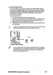
...to clear the RTC when the system hangs due to pins 2-3. Hold down and reboot the system so BIOS can clear the CMOS memory of date, time, and system setup parameters by the onboard button cell battery..... Turn OFF the computer and unplug the power cord. 2. Shut down the key during the boot process and enter BIOS setup to pins 1-2. 3. Clear RTC RAM (CLRTC1) This jumper allows you to overclocking, use the C.P.R. (CPU ... for about 5~10 seconds, then move the cap back to re-enter data. ASUS P4PE BP motherboard user guide 1-17 Keep the cap on CLRTC1 jumper default position. 3.
...to clear the RTC when the system hangs due to pins 2-3. Hold down and reboot the system so BIOS can clear the CMOS memory of date, time, and system setup parameters by the onboard button cell battery..... Turn OFF the computer and unplug the power cord. 2. Shut down the key during the boot process and enter BIOS setup to pins 1-2. 3. Clear RTC RAM (CLRTC1) This jumper allows you to overclocking, use the C.P.R. (CPU ... for about 5~10 seconds, then move the cap back to re-enter data. ASUS P4PE BP motherboard user guide 1-17 Keep the cap on CLRTC1 jumper default position. 3.

Motherboard DIY Troubleshooting Guide
Page 29
It is recommended that you connect the cables. 2. BIOS supports specific device bootup. If you must configure the second drive as a slave device by setting its thermal sensor cable to the UltraDMA/100/66 ... the gray connector to the UltraDMA/100/66 slave device (hard disk drive) and the black connector to this connector. ® P4PE BP TRPWR1 Ground TRPWR P4PE BP Power Supply Thermal Connector ASUS P4PE BP motherboard user guide 1-19 Refer to PIN 1. The hole near the blue connector on the UltraDMA/100/66 cable is removed to...
It is recommended that you connect the cables. 2. BIOS supports specific device bootup. If you must configure the second drive as a slave device by setting its thermal sensor cable to the UltraDMA/100/66 ... the gray connector to the UltraDMA/100/66 slave device (hard disk drive) and the black connector to this connector. ® P4PE BP TRPWR1 Ground TRPWR P4PE BP Power Supply Thermal Connector ASUS P4PE BP motherboard user guide 1-19 Refer to PIN 1. The hole near the blue connector on the UltraDMA/100/66 cable is removed to...

Motherboard DIY Troubleshooting Guide
Page 31
This requires an external detection mechanism such as shown in BIOS to use with intrusion detection feature. CHASSIS1 +5VSB_MB Chassis Signal GND ® P4PE BP P4PE BP Chassis Alarm Lead (Default) 7. Chassis intrusion connector (4-1 pin CHASSIS1) This lead is for use the chassis intrusion... module to the motherboard SIR connector according to the pin definitions. ® P4PE BP IR1 1 P4PE BP Infrared Module Connector +5V IRRX GND IRTX Front View Back View IRTX GND IRRX +5V (NC) ASUS P4PE BP motherboard user guide 1-21 When you wish to set UART2 for a chassis ...
This requires an external detection mechanism such as shown in BIOS to use with intrusion detection feature. CHASSIS1 +5VSB_MB Chassis Signal GND ® P4PE BP P4PE BP Chassis Alarm Lead (Default) 7. Chassis intrusion connector (4-1 pin CHASSIS1) This lead is for use the chassis intrusion... module to the motherboard SIR connector according to the pin definitions. ® P4PE BP IR1 1 P4PE BP Infrared Module Connector +5V IRRX GND IRTX Front View Back View IRTX GND IRRX +5V (NC) ASUS P4PE BP motherboard user guide 1-21 When you wish to set UART2 for a chassis ...

Motherboard DIY Troubleshooting Guide
Page 35
... Lead (2-pin SMI) This 2-pin connector allows you turn on the BIOS or OS settings. Keyboard Lock Speaker Power LED Connector +5 V PLED Keylock Ground +5V Ground Ground Speaker ExtSMI# Ground PWRBIN Ground Reset Ground ® P4PE BP Reset SW SMI Lead ATX Power Switch* * Requires an ATX power ...turns the system OFF. • Reset Switch Lead (2-pin RESET) This 2-pin connector connects to expand the life of certain system components. ASUS P4PE BP motherboard user guide 1-25 Pressing the power switch turns the system between ON and SLEEP, or ON and SOFT OFF, depending on the ...
... Lead (2-pin SMI) This 2-pin connector allows you turn on the BIOS or OS settings. Keyboard Lock Speaker Power LED Connector +5 V PLED Keylock Ground +5V Ground Ground Speaker ExtSMI# Ground PWRBIN Ground Reset Ground ® P4PE BP Reset SW SMI Lead ATX Power Switch* * Requires an ATX power ...turns the system OFF. • Reset Switch Lead (2-pin RESET) This 2-pin connector connects to expand the life of certain system components. ASUS P4PE BP motherboard user guide 1-25 Pressing the power switch turns the system between ON and SLEEP, or ON and SOFT OFF, depending on the ...

Motherboard DIY Troubleshooting Guide
Page 37
Chapter 2 This chapter tells how to change system settings through the BIOS Setup menus. BIOS information Detailed descriptions of the BIOS parameters are also provided.
Chapter 2 This chapter tells how to change system settings through the BIOS Setup menus. BIOS information Detailed descriptions of the BIOS parameters are also provided.

Motherboard DIY Troubleshooting Guide
Page 38
... need to display the following screen. The EZ Flash is recommended that contains the new BIOS file into the floppy drive. ASUS EZ Flash V1.00 Copyright (C) 2002, ASUSTeK COMPUTER INC. [Onboard BIOS Information] BIOS Version : ASUS P4PE BP ACPI BIOS Revision 1002 BIOS Model : P4PE BP BIOS Built Date : 04/16/02 Please Enter File Name for reference only. Follow these...
... need to display the following screen. The EZ Flash is recommended that contains the new BIOS file into the floppy drive. ASUS EZ Flash V1.00 Copyright (C) 2002, ASUSTeK COMPUTER INC. [Onboard BIOS Information] BIOS Version : ASUS P4PE BP ACPI BIOS Revision 1002 BIOS Model : P4PE BP BIOS Built Date : 04/16/02 Please Enter File Name for reference only. Follow these...

Motherboard DIY Troubleshooting Guide
Page 39
... you typed. Pressing N exits the EZ Flash screen and reboots the system without updating the BIOS. DO NOT shutdown or reset the system while updating the BIOS area! appears. ASUS P4PE BP motherboard user guide 2-3 Flash Memory: SST 49LF004 Update Main BIOS area (Y/N)? _ 7. When the update process is done, the message, "Press a key to update the...
... you typed. Pressing N exits the EZ Flash screen and reboots the system without updating the BIOS. DO NOT shutdown or reset the system while updating the BIOS area! appears. ASUS P4PE BP motherboard user guide 2-3 Flash Memory: SST 49LF004 Update Main BIOS area (Y/N)? _ 7. When the update process is done, the message, "Press a key to update the...

Motherboard DIY Troubleshooting Guide
Page 40
... memory drivers that may be programmed by the Flash Memory Writer utility. 2-4 Chapter 2: BIOS information AFLASH works only in the DOS prompt within Windows, and does not work in ... floppy disk. 3. Type COPY D:\AFLASH\AFLASH.EXE A:\ (assuming D is recommended that updates the BIOS by uploading a new BIOS file to the programmable flash ROM on the upper left-hand corner of your CD-ROM drive) to... copy AFLASH.EXE to the boot disk you created. To determine the BIOS version of your motherboard, check the last four numbers of the code displayed on the motherboard. ...
... memory drivers that may be programmed by the Flash Memory Writer utility. 2-4 Chapter 2: BIOS information AFLASH works only in the DOS prompt within Windows, and does not work in ... floppy disk. 3. Type COPY D:\AFLASH\AFLASH.EXE A:\ (assuming D is recommended that updates the BIOS by uploading a new BIOS file to the programmable flash ROM on the upper left-hand corner of your CD-ROM drive) to... copy AFLASH.EXE to the boot disk you created. To determine the BIOS version of your motherboard, check the last four numbers of the code displayed on the motherboard. ...

Motherboard DIY Troubleshooting Guide
Page 41
... At the "A:\" prompt, type AFLASH and then press . 4. The Save Current BIOS To File screen appears. 6. Type the filename of your problems. Careless updating may result to more problems with the motherboard! 1. ASUS P4PE BP motherboard user guide 2-5 Boot from the Main menu and press . XX.XXX, then... press . Download an updated ASUS BIOS file from the Internet (WWW or FTP) (see ASUS CONTACT INFORMATION on page viii for example, A:\XXX- ...
... At the "A:\" prompt, type AFLASH and then press . 4. The Save Current BIOS To File screen appears. 6. Type the filename of your problems. Careless updating may result to more problems with the motherboard! 1. ASUS P4PE BP motherboard user guide 2-5 Boot from the Main menu and press . XX.XXX, then... press . Download an updated ASUS BIOS file from the Internet (WWW or FTP) (see ASUS CONTACT INFORMATION on page viii for example, A:\XXX- ...

Motherboard DIY Troubleshooting Guide
Page 42
... the process, and if the problem persists, load the original BIOS file you encounter problems while updating the new BIOS, DO NOT turn off the system because this happens, call the ASUS service center for support. 2-6 Chapter 2: BIOS information The boot block is not able to program the new... BIOS information into the Flash ROM. If the Flash Memory Writer utility is updated automatically only when necessary. If ...
... the process, and if the problem persists, load the original BIOS file you encounter problems while updating the new BIOS, DO NOT turn off the system because this happens, call the ASUS service center for support. 2-6 Chapter 2: BIOS information The boot block is not able to program the new... BIOS information into the Flash ROM. If the Flash Memory Writer utility is updated automatically only when necessary. If ...

Motherboard DIY Troubleshooting Guide
Page 43
... you sure? (Y/N)" 4. Press Y to update the BIOS. Visit the ASUS website (www.asus.com) and download the latest BIOS for the procedure. 3. "The BIOS was corrupted! If the BIOS image is newer than the current BIOS, or if the BIOS is corrupted, this motherboard. 4. See section 2.1.2 for this confirmation message appears. ASUS P4PE BP motherboard user guide 2-7 Do you save a copy...
... you sure? (Y/N)" 4. Press Y to update the BIOS. Visit the ASUS website (www.asus.com) and download the latest BIOS for the procedure. 3. "The BIOS was corrupted! If the BIOS image is newer than the current BIOS, or if the BIOS is corrupted, this motherboard. 4. See section 2.1.2 for this confirmation message appears. ASUS P4PE BP motherboard user guide 2-7 Do you save a copy...

Motherboard DIY Troubleshooting Guide
Page 44
...features. You can also restart by pressing the reset button on your selections among the predetermined choices. It is highlighted. 2-8 Chapter 2: BIOS information Use this menu to configure the default system device used to the basic system configuration. The Flash ROM on the keyboard until ... Setup program is constantly being updated, the following selections: MAIN ADVANCED POWER BOOT EXIT Use this menu to run this utility. 2.2 BIOS Setup program This motherboard supports a programmable Flash ROM that the computer can recognize these changes and record them in the CMOS RAM of...
...features. You can also restart by pressing the reset button on your selections among the predetermined choices. It is highlighted. 2-8 Chapter 2: BIOS information Use this menu to configure the default system device used to the basic system configuration. The Flash ROM on the keyboard until ... Setup program is constantly being updated, the following selections: MAIN ADVANCED POWER BOOT EXIT Use this menu to run this utility. 2.2 BIOS Setup program This motherboard supports a programmable Flash ROM that the computer can recognize these changes and record them in the CMOS RAM of...

Motherboard DIY Troubleshooting Guide
Page 45
... document. Scroll bar When a scroll bar appears to the right of the Setup screen is more information to the Item Specific Help window, the BIOS setup program also provides a General Help screen. You may launch this screen from a sub-menu Selects the menu item to the last page.... or or Function Description Displays the General Help screen from anywhere in the legend bar allow you to scroll through the various setup menus. ASUS P4PE BP motherboard user guide 2-9 The following table lists the keys found in the window. The General Help screen lists the legend keys and their...
... document. Scroll bar When a scroll bar appears to the right of the Setup screen is more information to the Item Specific Help window, the BIOS setup program also provides a General Help screen. You may launch this screen from a sub-menu Selects the menu item to the last page.... or or Function Description Displays the General Help screen from anywhere in the legend bar allow you to scroll through the various setup menus. ASUS P4PE BP motherboard user guide 2-9 The following table lists the keys found in the window. The General Help screen lists the legend keys and their...


