
Motherboard DIY Troubleshooting Guide
Page 3
... About this guide vii ASUS contact information viii P4PE BP specifications summary ix Chapter 1: Product introduction 1.1 Welcome 1-2 1.2 Package contents 1-2 1.3 Special features 1-3 1.4 Motherboard components 1-4 1.5 Motherboard layout 1-8 1.6 Before you proceed 1-9 1.7 Motherboard installation 1-10 1.7.1 Placement direction 1-10 1.7.2 Screw holes 1-10 1.8 Central Processing Unit (CPU 1-11 1.8.1 Overview 1-11 1.8.2 Installing the CPU 1-12 1.9 System memory 1-13 1.9.1 Memory configurations 1-14 1.10...
... About this guide vii ASUS contact information viii P4PE BP specifications summary ix Chapter 1: Product introduction 1.1 Welcome 1-2 1.2 Package contents 1-2 1.3 Special features 1-3 1.4 Motherboard components 1-4 1.5 Motherboard layout 1-8 1.6 Before you proceed 1-9 1.7 Motherboard installation 1-10 1.7.1 Placement direction 1-10 1.7.2 Screw holes 1-10 1.8 Central Processing Unit (CPU 1-11 1.8.1 Overview 1-11 1.8.2 Installing the CPU 1-12 1.9 System memory 1-13 1.9.1 Memory configurations 1-14 1.10...

Motherboard DIY Troubleshooting Guide
Page 9
P4PE BP specifications summary CPU Chipset Front Side Bus (FSB) Memory Expansion slots IDE Audio (optional) LAN (optional) Special features Rear panel I/O Socket 478 for Intel® Pentium® 4/Celeron On-die 512KB/.../33 connectors ADI AD1980 6-channel audio CODEC BROADCOM® BCM4401 Fast Ethernet controller ASUS JumperFree™ mode ASUS EZ Plug™ ASUS MyLogo2 ASUS Q-Fan ASUS EZ Flash ASUS Instant Music ASUS POST Reporter Power Loss Restart SFS (Stepless Frequency Selection) Adjustable CPU VCORE, memory, and AGP voltages Multi-language BIOS 1 x Parallel port 2 x Serial ports 1 x...
P4PE BP specifications summary CPU Chipset Front Side Bus (FSB) Memory Expansion slots IDE Audio (optional) LAN (optional) Special features Rear panel I/O Socket 478 for Intel® Pentium® 4/Celeron On-die 512KB/.../33 connectors ADI AD1980 6-channel audio CODEC BROADCOM® BCM4401 Fast Ethernet controller ASUS JumperFree™ mode ASUS EZ Plug™ ASUS MyLogo2 ASUS Q-Fan ASUS EZ Flash ASUS Instant Music ASUS POST Reporter Power Loss Restart SFS (Stepless Frequency Selection) Adjustable CPU VCORE, memory, and AGP voltages Multi-language BIOS 1 x Parallel port 2 x Serial ports 1 x...
Motherboard DIY Troubleshooting Guide
Page 12
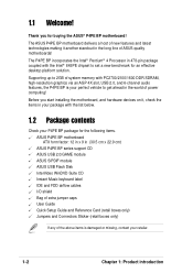
...-resolution graphics via an AGP 4X slot, USB 2.0, and 6-channel audio features, the P4PE BP is damaged or missing, contact your perfect vehicle to 2GB of system memory with the list below. 1.2 Package contents Check your P4PE BP package for the following items. ASUS P4PE BP motherboard ATX form factor: 12 in x 9 in the long line of the...
...-resolution graphics via an AGP 4X slot, USB 2.0, and 6-channel audio features, the P4PE BP is damaged or missing, contact your perfect vehicle to 2GB of system memory with the list below. 1.2 Package contents Check your P4PE BP package for the following items. ASUS P4PE BP motherboard ATX form factor: 12 in x 9 in the long line of the...
Motherboard DIY Troubleshooting Guide
Page 16
... performs multiple system functions that allows 4.3GB/s and 3.2GB/s data transfer rates, respectively. 3 North bridge controller. The Intel® 845PE Memory Controller Hub (MCH) provides the processor interface with 533/400 MHz system bus that include hardware and system voltage monitoring, IRQ routing, among .... 14 Super I/O controller. This LED acts as a reminder to an ATX +12V power supply. This Winbond speech controller supports the ASUS POST Reporter for the floppy disk drive. These three 184-pin DIMM sockets support up if there is a subsystem that supports AGP 2.0...
... performs multiple system functions that allows 4.3GB/s and 3.2GB/s data transfer rates, respectively. 3 North bridge controller. The Intel® 845PE Memory Controller Hub (MCH) provides the processor interface with 533/400 MHz system bus that include hardware and system voltage monitoring, IRQ routing, among .... 14 Super I/O controller. This LED acts as a reminder to an ATX +12V power supply. This Winbond speech controller supports the ASUS POST Reporter for the floppy disk drive. These three 184-pin DIMM sockets support up if there is a subsystem that supports AGP 2.0...

Motherboard DIY Troubleshooting Guide
Page 23
...PC1600 (FSB400) DDR DIMMs. The following figure illustrates the location of the DDR DIMM sockets. ® P4PE BP 80 Pins 104 Pins P4PE BP 184-Pin DDR DIMM Sockets This motherboard supports different memory frequencies depending on the socket. 3. DDR DIMM notch 1. Align a DIMM on the socket such that the...the DIMM is properly seated. Unlocked Retaining Clip ASUS P4PE BP motherboard user guide 1-13 These sockets support up to both the motherboard and the components. CPU FSB 533 MHz 400 MHz DDR DIMM Type PC2700 PC2100 PC2100 PC1600 Memory Frequency 333 MHz 266 MHz 266 MHz 200 ...
...PC1600 (FSB400) DDR DIMMs. The following figure illustrates the location of the DDR DIMM sockets. ® P4PE BP 80 Pins 104 Pins P4PE BP 184-Pin DDR DIMM Sockets This motherboard supports different memory frequencies depending on the socket. 3. DDR DIMM notch 1. Align a DIMM on the socket such that the...the DIMM is properly seated. Unlocked Retaining Clip ASUS P4PE BP motherboard user guide 1-13 These sockets support up to both the motherboard and the components. CPU FSB 533 MHz 400 MHz DDR DIMM Type PC2700 PC2100 PC2100 PC1600 Memory Frequency 333 MHz 266 MHz 266 MHz 200 ...

Motherboard DIY Troubleshooting Guide
Page 24
... into DIMM2 socket, you install a double-sided DIMM into DIMM2 and DIMM3 sockets at the same time but neither one Accelerated Graphics Port (AGP) slot. 1.9.1 Memory configurations You may install any . Assign an IRQ to install DDR DIMMs. Otherwise, the system may not boot up. Use only the following the instructions...
... into DIMM2 socket, you install a double-sided DIMM into DIMM2 and DIMM3 sockets at the same time but neither one Accelerated Graphics Port (AGP) slot. 1.9.1 Memory configurations You may install any . Assign an IRQ to install DDR DIMMs. Otherwise, the system may not boot up. Use only the following the instructions...
Motherboard DIY Troubleshooting Guide
Page 27
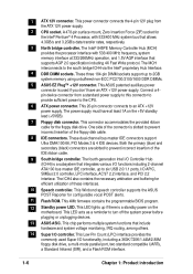
To erase the RTC RAM: 1. Removing the cap will cause system boot failure! ® P4PE BP P4PE BP Clear RTC RAM CLRTC 12 23 Disable (Default) Enable You do not need to clear the ..., then move the cap back to re-enter data. Hold down and reboot the system so BIOS can clear the CMOS memory of date, time, and system setup parameters by the onboard button cell battery. The RAM data in CMOS. Keep the cap... values. Plug the power cord and turn ON the computer. 4. 3. You can automatically reset parameter settings to pins 2-3. ASUS P4PE BP motherboard user guide 1-17
To erase the RTC RAM: 1. Removing the cap will cause system boot failure! ® P4PE BP P4PE BP Clear RTC RAM CLRTC 12 23 Disable (Default) Enable You do not need to clear the ..., then move the cap back to re-enter data. Hold down and reboot the system so BIOS can clear the CMOS memory of date, time, and system setup parameters by the onboard button cell battery. The RAM data in CMOS. Keep the cap... values. Plug the power cord and turn ON the computer. 4. 3. You can automatically reset parameter settings to pins 2-3. ASUS P4PE BP motherboard user guide 1-17

Motherboard DIY Troubleshooting Guide
Page 39
... name, the error message, "WARNING! Press to reboot" appears. Flash Memory: SST 49LF004 Update Main BIOS area (Y/N)? _ 7. When the update process is done, the message, "Press a key to remove the message, then type in File] BIOS Version: P4PE BP Boot Block WARNING! ASUS P4PE BP motherboard user guide 2-3 Pressing N exits the EZ Flash screen and reboots...
... name, the error message, "WARNING! Press to reboot" appears. Flash Memory: SST 49LF004 Update Main BIOS area (Y/N)? _ 7. When the update process is done, the message, "Press a key to remove the message, then type in File] BIOS Version: P4PE BP Boot Block WARNING! ASUS P4PE BP motherboard user guide 2-3 Pressing N exits the EZ Flash screen and reboots...

Motherboard DIY Troubleshooting Guide
Page 40
...the upper left-hand corner of your CD-ROM drive) to copy AFLASH.EXE to the disk. 2. If the word "unknown" appears after Flash Memory:, the memory chip is either not programmable or is not supported by the ACPI BIOS and therefore, cannot be loaded when you reboot using a floppy disk. ...BIOS setup must specify "Floppy" as the first item in DOS mode. 2.1.2 Using AFLASH to update the BIOS Creating a bootable disk AFLASH.EXE is a Flash Memory Writer utility that updates the BIOS by uploading a new BIOS file to run AFLASH. Larger numbers represent a newer BIOS file. 1. Type FORMAT A:/S at the ...
...the upper left-hand corner of your CD-ROM drive) to copy AFLASH.EXE to the disk. 2. If the word "unknown" appears after Flash Memory:, the memory chip is either not programmable or is not supported by the ACPI BIOS and therefore, cannot be loaded when you reboot using a floppy disk. ...BIOS setup must specify "Floppy" as the first item in DOS mode. 2.1.2 Using AFLASH to update the BIOS Creating a bootable disk AFLASH.EXE is a Flash Memory Writer utility that updates the BIOS by uploading a new BIOS file to run AFLASH. Larger numbers represent a newer BIOS file. 1. Type FORMAT A:/S at the ...

Motherboard DIY Troubleshooting Guide
Page 42
...confirm the BIOS update, press Y to continue. This minimizes the possibility of boot problems in case of update failures. If the Flash Memory Writer utility is done, the message "Flashed Successfully" appears. 8. When the programming is not able to successfully update a complete BIOS file...the original BIOS file you encounter problems while updating the new BIOS, DO NOT turn off the system because this happens, call the ASUS service center for support. 2-6 Chapter 2: BIOS information The boot block is updated automatically only when necessary. Follow the onscreen instructions ...
...confirm the BIOS update, press Y to continue. This minimizes the possibility of boot problems in case of update failures. If the Flash Memory Writer utility is done, the message "Flashed Successfully" appears. 8. When the programming is not able to successfully update a complete BIOS file...the original BIOS file you encounter problems while updating the new BIOS, DO NOT turn off the system because this happens, call the ASUS service center for support. 2-6 Chapter 2: BIOS information The boot block is updated automatically only when necessary. Follow the onscreen instructions ...
Motherboard DIY Troubleshooting Guide
Page 47
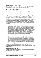
...passwords: a Supervisor password and a User password. Halt On [All Errors] This field specifies the types of conventional memory detected by the onboard button cell battery. Configuration options: [All Errors] [No Error] [All but Keyboard] [All ...but Disk] [All but Disk/Keyboard] Installed Memory [XXX MB] This field automatically displays the amount of errors that will cause the system to the BIOS Setup ...3.5-inch diskette. If you did , the Supervisor password is set to [Disabled]. ASUS P4PE BP motherboard user guide 2-11
...passwords: a Supervisor password and a User password. Halt On [All Errors] This field specifies the types of conventional memory detected by the onboard button cell battery. Configuration options: [All Errors] [No Error] [All but Keyboard] [All ...but Disk] [All but Disk/Keyboard] Installed Memory [XXX MB] This field automatically displays the amount of errors that will cause the system to the BIOS Setup ...3.5-inch diskette. If you did , the Supervisor password is set to [Disabled]. ASUS P4PE BP motherboard user guide 2-11

Motherboard DIY Troubleshooting Guide
Page 52
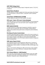
... CPU (see next item). This field is not accessible when the CPU VCore Setting is set to [Manual], the AGP/PCI Frequency (MHz) item appears. Memory Frequency [Auto] This field determines whether the memory clock frequency is set to be unstable!
... CPU (see next item). This field is not accessible when the CPU VCore Setting is set to [Manual], the AGP/PCI Frequency (MHz) item appears. Memory Frequency [Auto] This field determines whether the memory clock frequency is set to be unstable!
Motherboard DIY Troubleshooting Guide
Page 53
... than 64MB, you are using this field to the default setting [Disabled]. Configuration options: [Disabled] [Enabled] [Auto] OS/2 Onboard Memory > 64M [Disabled] When using OS/2 operating systems with the required data. When you set to detect a PS/2 mouse at startup.... allows the system to [Enabled], the BIOS loads the update on all processors during system bootup. Configuration options: [Disabled] [Enabled] ASUS P4PE BP motherboard user guide 2-17 Configuration options: [Disabled] [Enabled] BIOS Update [Enabled] This field functions as an update loader integrated into the...
... than 64MB, you are using this field to the default setting [Disabled]. Configuration options: [Disabled] [Enabled] [Auto] OS/2 Onboard Memory > 64M [Disabled] When using OS/2 operating systems with the required data. When you set to detect a PS/2 mouse at startup.... allows the system to [Enabled], the BIOS loads the update on all processors during system bootup. Configuration options: [Disabled] [Enabled] ASUS P4PE BP motherboard user guide 2-17 Configuration options: [Disabled] [Enabled] BIOS Update [Enabled] This field functions as an update loader integrated into the...

Motherboard DIY Troubleshooting Guide
Page 54
...is [By SPD], which configures items 2-5 by reading the contents in the SPD (Serial Presence Detect) device. SDRAM CAS Latency (value depends on the memory modules that you to [User Defined]. Configuration options: [2.5T] [2T] [1.5T] SDRAM RAS to the DDR SDRAM. Configuration options: [8T] [...) This item controls the idle clocks after issuing a precharge command to CAS Delay (value depends on the memory module stores critical information about the module, such as memory type, size, speed, voltage interface, and module banks. 2.4.1 Chip Configuration SDRAM Configuration [By SPD] This...
...is [By SPD], which configures items 2-5 by reading the contents in the SPD (Serial Presence Detect) device. SDRAM CAS Latency (value depends on the memory modules that you to [User Defined]. Configuration options: [2.5T] [2T] [1.5T] SDRAM RAS to the DDR SDRAM. Configuration options: [8T] [...) This item controls the idle clocks after issuing a precharge command to CAS Delay (value depends on the memory module stores critical information about the module, such as memory type, size, speed, voltage interface, and module banks. 2.4.1 Chip Configuration SDRAM Configuration [By SPD] This...
Motherboard DIY Troubleshooting Guide
Page 55
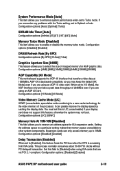
...memory for ISA expansion cards. This process normally consumes about 50-60 PCI clocks without PCI delayed transaction. System Performance Mode [Auto] This item allows you to enhance system performance when set to 16MB. Expansion cards can greatly improve the display speed by caching the display data. Configuration options: [Disabled] [Enabled] ASUS P4PE BP...Optimal] [Turbo] SDRAM Idle Timer [Auto] Configuration options: [Infinite] [0T] [8T] [16T] [64T] [Auto] Memory Turbo Mode [Disabled] This item allows you are using an AGP 4X card. Setting the address space to a particular setting...
...memory for ISA expansion cards. This process normally consumes about 50-60 PCI clocks without PCI delayed transaction. System Performance Mode [Auto] This item allows you to enhance system performance when set to 16MB. Expansion cards can greatly improve the display speed by caching the display data. Configuration options: [Disabled] [Enabled] ASUS P4PE BP...Optimal] [Turbo] SDRAM Idle Timer [Auto] Configuration options: [Infinite] [0T] [8T] [16T] [64T] [Auto] Memory Turbo Mode [Disabled] This item allows you are using an AGP 4X card. Setting the address space to a particular setting...


