Motherboard DIY Troubleshooting Guide
Page 12
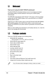
... keyboard label IDE and FDD airflow cables I/O shield Bag of extra jumper caps User Guide Quick Setup Guide and Reference Card (retail boxes only) Jumpers and Connectors Sticker (retail boxes only) If any of ASUS quality motherboards! Before you for the following items. ASUS P4PE BP motherboard ATX form factor: 12 in x 9 in 478-pin package coupled with PC2700/2100/1600 DDR SDRAM, high-resolution graphics via an AGP 4X slot, USB 2.0, and 6-channel audio...
... keyboard label IDE and FDD airflow cables I/O shield Bag of extra jumper caps User Guide Quick Setup Guide and Reference Card (retail boxes only) Jumpers and Connectors Sticker (retail boxes only) If any of ASUS quality motherboards! Before you for the following items. ASUS P4PE BP motherboard ATX form factor: 12 in x 9 in 478-pin package coupled with PC2700/2100/1600 DDR SDRAM, high-resolution graphics via an AGP 4X slot, USB 2.0, and 6-channel audio...
Motherboard DIY Troubleshooting Guide
Page 13
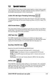
... removable flash disk allows you to mobilize your data so easily. See page 3-10. ASUS P4PE BP motherboard user guide 1-3 See page 3-8 for MPEG 1&2 video editing Airflow cable These IDE/FDD cables take system cabling to a new dimension. Just press the ASUS Instant Music special function keys and enjoy the music! The compressed design eliminates cable clutter within the chassis, thus optimizing internal airflow. With easily removable color-coded pull-tab connectors, connecting devices...
... removable flash disk allows you to mobilize your data so easily. See page 3-10. ASUS P4PE BP motherboard user guide 1-3 See page 3-8 for MPEG 1&2 video editing Airflow cable These IDE/FDD cables take system cabling to a new dimension. Just press the ASUS Instant Music special function keys and enjoy the music! The compressed design eliminates cable clutter within the chassis, thus optimizing internal airflow. With easily removable color-coded pull-tab connectors, connecting devices...
Motherboard DIY Troubleshooting Guide
Page 16
... and system voltage monitoring, IRQ routing, among others. 14 Super I /O APIC, SMBus 2.0 controller, LPC interface, AC'97 2.2 interface, and PCI 2.2 interface. Connect a 4pin device connector from the ATX 12V power supply. 2 CPU socket. These dual-channel bus master IDE connectors support Ultra DMA/100/66, PIO Modes 3 & 4 IDE devices. This 4Mb firmware contains the programmable BIOS program. 12 Standby power LED. The power supply must have an ATX +12V power supply. This ASUS patented auxilliary power connector is slotted to 2GB system memory using unbuffered non...
... and system voltage monitoring, IRQ routing, among others. 14 Super I /O APIC, SMBus 2.0 controller, LPC interface, AC'97 2.2 interface, and PCI 2.2 interface. Connect a 4pin device connector from the ATX 12V power supply. 2 CPU socket. These dual-channel bus master IDE connectors support Ultra DMA/100/66, PIO Modes 3 & 4 IDE devices. This 4Mb firmware contains the programmable BIOS program. 12 Standby power LED. The power supply must have an ATX +12V power supply. This ASUS patented auxilliary power connector is slotted to 2GB system memory using unbuffered non...

Motherboard DIY Troubleshooting Guide
Page 23
... the power supply before adding or removing DIMMs or other system components. Follow these steps to 2GB system memory using 184-pin unbuffered non-ECC PC2700/PC2100 (FSB533) or PC2100/PC1600 (FSB400) DDR DIMMs. The following figure illustrates the location of the DDR DIMM sockets. ® P4PE BP 80 Pins 104 Pins P4PE BP 184-Pin DDR DIMM Sockets This motherboard supports different memory frequencies depending on the socket. 3. Unlock a DIMM socket...
... the power supply before adding or removing DIMMs or other system components. Follow these steps to 2GB system memory using 184-pin unbuffered non-ECC PC2700/PC2100 (FSB533) or PC2100/PC1600 (FSB400) DDR DIMMs. The following figure illustrates the location of the DDR DIMM sockets. ® P4PE BP 80 Pins 104 Pins P4PE BP 184-Pin DDR DIMM Sockets This motherboard supports different memory frequencies depending on the socket. 3. Unlock a DIMM socket...
Motherboard DIY Troubleshooting Guide
Page 27
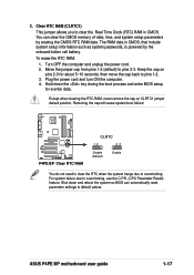
... automatically reset parameter settings to default values. The RAM data in CMOS. For system failure due to overclocking. ASUS P4PE BP motherboard user guide 1-17 Except when clearing the RTC RAM, never remove the cap on pins 2-3 for about 5~10 seconds, then move the cap back to re-enter data. Move the jumper cap from pins 1-2 (default) to clear the Real Time Clock (RTC) RAM in CMOS, that include system setup information such as system passwords, is powered...
... automatically reset parameter settings to default values. The RAM data in CMOS. For system failure due to overclocking. ASUS P4PE BP motherboard user guide 1-17 Except when clearing the RTC RAM, never remove the cap on pins 2-3 for about 5~10 seconds, then move the cap back to re-enter data. Move the jumper cap from pins 1-2 (default) to clear the Real Time Clock (RTC) RAM in CMOS, that include system setup information such as system passwords, is powered...

Motherboard DIY Troubleshooting Guide
Page 29
.../100/66 devices, purchase another for the primary IDE connector and another UltraDMA/100/66 cable. 3. You may configure two hard disks to this connector. ® P4PE BP TRPWR1 Ground TRPWR P4PE BP Power Supply Thermal Connector ASUS P4PE BP motherboard user guide 1-19 It is intentional. ® P4PE BP NOTE: Orient the red markings (usually zigzag) on the UltraDMA cable connector. one for the secondary IDE connector. 1. Power supply thermal connector (2-pin TRPWR1) If your power supply has a thermal monitoring feature, connect its jumper accordingly.
.../100/66 devices, purchase another for the primary IDE connector and another UltraDMA/100/66 cable. 3. You may configure two hard disks to this connector. ® P4PE BP TRPWR1 Ground TRPWR P4PE BP Power Supply Thermal Connector ASUS P4PE BP motherboard user guide 1-19 It is intentional. ® P4PE BP NOTE: Orient the red markings (usually zigzag) on the UltraDMA cable connector. one for the secondary IDE connector. 1. Power supply thermal connector (2-pin TRPWR1) If your power supply has a thermal monitoring feature, connect its jumper accordingly.
Motherboard DIY Troubleshooting Guide
Page 33
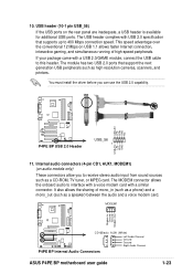
... Right Audio Channel P4PE BP Internal Audio Connectors ASUS P4PE BP motherboard user guide 1-23 USB+5V LP5LP5+ GND NC ® P4PE BP P4PE BP USB 2.0 Header USB_56 1 USB+5V LP4LP4+ GND 11. The USB header complies with a similar connector. If your package came with a USB 2.0/GAME module, connect the USB cable to receive stereo audio input from sound sources such as high resolution cameras, scanners, and printers. Internal audio connectors (4-pin CD1, AUX1, MODEM1) (on the rear panel are inadequate, a USB header is available for additional USB ports. It...
... Right Audio Channel P4PE BP Internal Audio Connectors ASUS P4PE BP motherboard user guide 1-23 USB+5V LP5LP5+ GND NC ® P4PE BP P4PE BP USB 2.0 Header USB_56 1 USB+5V LP4LP4+ GND 11. The USB header complies with a similar connector. If your package came with a USB 2.0/GAME module, connect the USB cable to receive stereo audio input from sound sources such as high resolution cameras, scanners, and printers. Internal audio connectors (4-pin CD1, AUX1, MODEM1) (on the rear panel are inadequate, a USB header is available for additional USB ports. It...

Motherboard DIY Troubleshooting Guide
Page 35
... 2-pin connector allows you to manually place the system into a suspend mode, or "green" mode, where system activity is in the ON mode for rebooting the system without turning off the system power. ASUS P4PE BP motherboard user guide 1-25 Keyboard Lock Speaker Power LED Connector +5 V PLED Keylock Ground +5V Ground Ground Speaker ExtSMI# Ground PWRBIN Ground Reset Ground ® P4PE BP Reset SW SMI Lead ATX Power Switch* * Requires an ATX power supply. 14. System panel connector (20-pin PANEL1) This connector accommodates...
... 2-pin connector allows you to manually place the system into a suspend mode, or "green" mode, where system activity is in the ON mode for rebooting the system without turning off the system power. ASUS P4PE BP motherboard user guide 1-25 Keyboard Lock Speaker Power LED Connector +5 V PLED Keylock Ground +5V Ground Ground Speaker ExtSMI# Ground PWRBIN Ground Reset Ground ® P4PE BP Reset SW SMI Lead ATX Power Switch* * Requires an ATX power supply. 14. System panel connector (20-pin PANEL1) This connector accommodates...

Motherboard DIY Troubleshooting Guide
Page 44
... back on. Use the BIOS Setup program when you wish to configure and enable Power Management features. The Setup program is constantly being updated, the following selections: MAIN ADVANCED POWER BOOT EXIT Use this menu to enable and make changes to locate and load the Operating System. Use this menu to configure the default system device used to the power management settings. Use this program. This section explains how to "Run Setup". The Flash ROM on the keyboard until the...
... back on. Use the BIOS Setup program when you wish to configure and enable Power Management features. The Setup program is constantly being updated, the following selections: MAIN ADVANCED POWER BOOT EXIT Use this menu to enable and make changes to locate and load the Operating System. Use this menu to configure the default system device used to the power management settings. Use this program. This section explains how to "Run Setup". The Flash ROM on the keyboard until the...
Motherboard DIY Troubleshooting Guide
Page 47
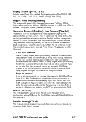
.... ASUS P4PE BP motherboard user guide 2-11 The password is set passwords. The RAM data containing the password information is required to enter the BIOS Setup program and to gain full access to [Enabled]. Refer to section "2.1 Managing and updating your password, you need to [Disabled]. Legacy Diskette A [1.44M, 3.5 in.] Sets the type of conventional memory detected by the onboard button cell battery. Type in a password then press . A note about 2 seconds, then power up to the BIOS Setup menus. The BIOS Setup program...
.... ASUS P4PE BP motherboard user guide 2-11 The password is set passwords. The RAM data containing the password information is required to enter the BIOS Setup program and to gain full access to [Enabled]. Refer to section "2.1 Managing and updating your password, you need to [Disabled]. Legacy Diskette A [1.44M, 3.5 in.] Sets the type of conventional memory detected by the onboard button cell battery. Type in a password then press . A note about 2 seconds, then power up to the BIOS Setup menus. The BIOS Setup program...

Motherboard DIY Troubleshooting Guide
Page 49
... new IDE hard disk drives. To make changes to this field, set the Type field to [User Type HDD] and the Translation Method field to the Main menu. When the Main menu appears, the hard disk drive field displays the size for the hard disk drive that LBA Mode is used without regard for the Type field are removing a drive and not replacing it, select [None]. To make changes to [Manual]. Other options for cylinders, heads, or sectors. ASUS P4PE BP motherboard user guide 2-13 This is installed...
... new IDE hard disk drives. To make changes to this field, set the Type field to [User Type HDD] and the Translation Method field to the Main menu. When the Main menu appears, the hard disk drive field displays the size for the hard disk drive that LBA Mode is used without regard for the Type field are removing a drive and not replacing it, select [None]. To make changes to [Manual]. Other options for cylinders, heads, or sectors. ASUS P4PE BP motherboard user guide 2-13 This is installed...
Motherboard DIY Troubleshooting Guide
Page 53
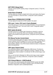
... data. Configuration options: [Disabled] [Enabled] [Auto] OS/2 Onboard Memory > 64M [Disabled] When using this option to detect a PS/2 mouse at startup. Configuration options: [Enabled] [Auto] USB Legacy Support [Auto] This motherboard supports Universal Serial Bus (USB) devices. Configuration options: [Disabled] [Enabled] ASUS P4PE BP motherboard user guide 2-17 Configuration options: [Disabled] [Enabled] Instant Music CDROM [ASUS CD-ROM] This item displays the detected CD-ROM installed in cache. If not detected, the USB controller legacy mode is disabled. When set this field...
... data. Configuration options: [Disabled] [Enabled] [Auto] OS/2 Onboard Memory > 64M [Disabled] When using this option to detect a PS/2 mouse at startup. Configuration options: [Enabled] [Auto] USB Legacy Support [Auto] This motherboard supports Universal Serial Bus (USB) devices. Configuration options: [Disabled] [Enabled] ASUS P4PE BP motherboard user guide 2-17 Configuration options: [Disabled] [Enabled] Instant Music CDROM [ASUS CD-ROM] This item displays the detected CD-ROM installed in cache. If not detected, the USB controller legacy mode is disabled. When set this field...
Motherboard DIY Troubleshooting Guide
Page 55
...-compatible, so you may not boot. It can only access memory up to 16MB. Configuration options: [UC] [USWC] Memory Hole At 15M-16M [Disabled] This field allows you to reserve an address space for the video memory of the processor. Setting the address space to a particular setting makes that transfers video data at 1066MB/s. This process normally consumes about 50-60 PCI clocks without PCI delayed transaction. Configuration options: [Disabled] [Enabled] ASUS P4PE BP motherboard user guide...
...-compatible, so you may not boot. It can only access memory up to 16MB. Configuration options: [UC] [USWC] Memory Hole At 15M-16M [Disabled] This field allows you to reserve an address space for the video memory of the processor. Setting the address space to a particular setting makes that transfers video data at 1066MB/s. This process normally consumes about 50-60 PCI clocks without PCI delayed transaction. Configuration options: [Disabled] [Enabled] ASUS P4PE BP motherboard user guide...

Motherboard DIY Troubleshooting Guide
Page 57
...port DMA channel for the selected ECP mode. Configuration options: [Disabled] [Enabled] Report IDE Error [Enabled] This item allows you to enable or disable system boot reporting. Configuration options: [Disabled] [Enabled] Report System Booting [Enabled] This item allows you to enable or disable IDE error reporting. Configuration options: [1] [3] Onboard AC97 Audio Controller [Auto] [Auto] allows the BIOS to detect whether you to enable or disable system check reporting. Configuration options: [Disabled] [Enabled] ASUS P4PE BP motherboard user guide 2-21 Configuration options...
...port DMA channel for the selected ECP mode. Configuration options: [Disabled] [Enabled] Report IDE Error [Enabled] This item allows you to enable or disable system boot reporting. Configuration options: [Disabled] [Enabled] Report System Booting [Enabled] This item allows you to enable or disable IDE error reporting. Configuration options: [1] [3] Onboard AC97 Audio Controller [Auto] [Auto] allows the BIOS to detect whether you to enable or disable system check reporting. Configuration options: [Disabled] [Enabled] ASUS P4PE BP motherboard user guide 2-21 Configuration options...

Motherboard DIY Troubleshooting Guide
Page 58
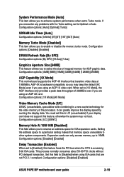
...USB 1.1 controllers that you to enable or disable the onboard LAN controller. Configuration options: [PCI VGA Card] [AGP VGA Card] [Onboard VGA] Onboard LAN Controller [Enabled] (appears on LAN models only) This field allows you wish to activate. If you to select the primary graphics card. Configuration options: [Disabled] [Enabled] PCI Latency Timer [32] Leave this field to the default setting [32] for each PCI slot. Configuration options: [Disabled] [Enabled] Primary VGA BIOS [PCI VGA Card] This field allows you are using standard VGA cards, leave this problem. The default setting...
...USB 1.1 controllers that you to enable or disable the onboard LAN controller. Configuration options: [PCI VGA Card] [AGP VGA Card] [Onboard VGA] Onboard LAN Controller [Enabled] (appears on LAN models only) This field allows you wish to activate. If you to select the primary graphics card. Configuration options: [Disabled] [Enabled] PCI Latency Timer [32] Leave this field to the default setting [32] for each PCI slot. Configuration options: [Disabled] [Enabled] Primary VGA BIOS [PCI VGA Card] This field allows you are using standard VGA cards, leave this problem. The default setting...
Motherboard DIY Troubleshooting Guide
Page 59
... not the displayed IRQ for an IRQ field indicates that this particular IRQ is being used by a legacy ISA card. Set the IRQ field to enable or disable the option ROM in the onboard LAN controller chipset. Configuration options: [No/ICU] [Yes] ASUS P4PE BP motherboard user guide 2-23 Onboard LAN Boot ROM [Disabled] (appears on LAN models only) This field allows you to [Yes] if you install a legacy ISA card that requires a unique IRQ and you are using the ISA Configuration Utility (ICU...
... not the displayed IRQ for an IRQ field indicates that this particular IRQ is being used by a legacy ISA card. Set the IRQ field to enable or disable the option ROM in the onboard LAN controller chipset. Configuration options: [No/ICU] [Yes] ASUS P4PE BP motherboard user guide 2-23 Onboard LAN Boot ROM [Disabled] (appears on LAN models only) This field allows you to [Yes] if you install a legacy ISA card that requires a unique IRQ and you are using the ISA Configuration Utility (ICU...
Motherboard DIY Troubleshooting Guide
Page 71
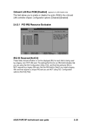
... Intel chipset components. ASUS P4PE BP motherboard user guide 3-3 Refer to the online help or readme file that outline to the target system the Windows INF files that came with the utility. Intel Chipset Inf Update program This item installs the Intel® Chipset INF Update Program that the motherboard supports. This program is designed to support 10BASE-T/ 100BASE-TX networking. 3.2.3 Utilities menu The Utilities menu shows the applications and other software that enables Plug-n-Play INF support...
... Intel chipset components. ASUS P4PE BP motherboard user guide 3-3 Refer to the online help or readme file that outline to the target system the Windows INF files that came with the utility. Intel Chipset Inf Update program This item installs the Intel® Chipset INF Update Program that the motherboard supports. This program is designed to support 10BASE-T/ 100BASE-TX networking. 3.2.3 Utilities menu The Utilities menu shows the applications and other software that enables Plug-n-Play INF support...
Motherboard DIY Troubleshooting Guide
Page 72
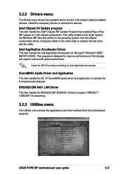
... smart utility monitors the fan speed, CPU temperature, and system voltages, and alerts you on page viii of the BIOS from the ASUS website. You may also find this user guide. 3-4 Chapter 3: Software support Before using the ASUS Update, make sure that gives online gamers the competitive edge in Portable Document Format (PDF). This application removes dark washed-out graphics to download the latest version of this information on any detected problems. This utility...
... smart utility monitors the fan speed, CPU temperature, and system voltages, and alerts you on page viii of the BIOS from the ASUS website. You may also find this user guide. 3-4 Chapter 3: Software support Before using the ASUS Update, make sure that gives online gamers the competitive edge in Portable Document Format (PDF). This application removes dark washed-out graphics to download the latest version of this information on any detected problems. This utility...
Motherboard DIY Troubleshooting Guide
Page 73
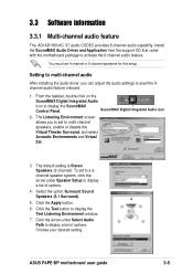
...-channel speakers, enable or disable the Virtual Theater Surround, and select Acoustic Environments and Virtual Ear. 3. The default setting is Stereo Speakers (2-channel). Select the option Surround Sound Speakers (5.1 Surround). 5. Click the Apply button. 6. Install the SoundMAX Audio Driver and Application from the support CD that came with the motherboard package to display the SoundMAX Control Panel. From the taskbar, double-click on the SoundMAX Digital Integrated Audio icon to activate the 6-channel audio feature. ASUS P4PE BP motherboard user guide 3-5 Sound MAX...
...-channel speakers, enable or disable the Virtual Theater Surround, and select Acoustic Environments and Virtual Ear. 3. The default setting is Stereo Speakers (2-channel). Select the option Surround Sound Speakers (5.1 Surround). 5. Click the Apply button. 6. Install the SoundMAX Audio Driver and Application from the support CD that came with the motherboard package to display the SoundMAX Control Panel. From the taskbar, double-click on the SoundMAX Digital Integrated Audio icon to activate the 6-channel audio feature. ASUS P4PE BP motherboard user guide 3-5 Sound MAX...

Motherboard DIY Troubleshooting Guide
Page 76
... LED is supported by pressing the Delete key during the Power On Self-Tests (POST). 3. This feature is fixed to Enabled. 4. Make sure to display the CD-ROM options. Turn on the system and enter BIOS by the onboard audio AC'97 CODEC, and requires an optical drive (CD-ROM, DVDROM, or CD-RW). 1. When set it to ON after enabling Instant Music. 2. A "beep" indicates this case, power up features (LAN, keyboard, mouse, USB...
... LED is supported by pressing the Delete key during the Power On Self-Tests (POST). 3. This feature is fixed to Enabled. 4. Make sure to display the CD-ROM options. Turn on the system and enter BIOS by the onboard audio AC'97 CODEC, and requires an optical drive (CD-ROM, DVDROM, or CD-RW). 1. When set it to ON after enabling Instant Music. 2. A "beep" indicates this case, power up features (LAN, keyboard, mouse, USB...


