
Motherboard DIY Troubleshooting Guide
Page 1
Motherboard P4PE BP User Guide
Motherboard P4PE BP User Guide

Motherboard DIY Troubleshooting Guide
Page 3
Features Contents Notices v Safety information vi About this guide vii ASUS contact information viii P4PE BP specifications summary ix Chapter 1: Product introduction 1.1 Welcome 1-2 1.2 Package contents 1-2 1.3 Special features 1-3 1.4 Motherboard components 1-4 1.5 Motherboard layout 1-8 1.6 Before you proceed 1-9 1.7 Motherboard installation 1-10 1.7.1 Placement direction 1-10 1.7.2 Screw holes 1-10 1.8 Central Processing Unit (CPU 1-11 1.8.1 Overview 1-11 1.8.2 Installing the CPU 1-12 1.9 System memory 1-13...
Features Contents Notices v Safety information vi About this guide vii ASUS contact information viii P4PE BP specifications summary ix Chapter 1: Product introduction 1.1 Welcome 1-2 1.2 Package contents 1-2 1.3 Special features 1-3 1.4 Motherboard components 1-4 1.5 Motherboard layout 1-8 1.6 Before you proceed 1-9 1.7 Motherboard installation 1-10 1.7.1 Placement direction 1-10 1.7.2 Screw holes 1-10 1.8 Central Processing Unit (CPU 1-11 1.8.1 Overview 1-11 1.8.2 Installing the CPU 1-12 1.9 System memory 1-13...

Motherboard DIY Troubleshooting Guide
Page 6
Operation safety • Before installing the motherboard and adding devices on it may become wet. • Place the product on a stable surface. • If you encounter technical problems with the package. • ... to the correct voltage in any damage, contact your dealer immediately. • To avoid short circuits, keep paper clips, screws, and staples away from the motherboard, ensure that all the manuals that came with the product, contact a qualified service technician or your retailer. vi If you are not sure about the...
Operation safety • Before installing the motherboard and adding devices on it may become wet. • Place the product on a stable surface. • If you encounter technical problems with the package. • ... to the correct voltage in any damage, contact your dealer immediately. • To avoid short circuits, keep paper clips, screws, and staples away from the motherboard, ensure that all the manuals that came with the product, contact a qualified service technician or your retailer. vi If you are not sure about the...

Motherboard DIY Troubleshooting Guide
Page 11
It includes brief descriptions of the motherboard components, and illustrations of the P4PE BP motherboard. Product introduction Chapter 1 This chapter describes the features of the layout, jumper settings, and connectors.
It includes brief descriptions of the motherboard components, and illustrations of the P4PE BP motherboard. Product introduction Chapter 1 This chapter describes the features of the layout, jumper settings, and connectors.
Motherboard DIY Troubleshooting Guide
Page 12
...via an AGP 4X slot, USB 2.0, and 6-channel audio features, the P4PE BP is damaged or missing, contact your perfect vehicle to set a new benchmark for buying the ASUS® P4PE BP motherboard! The ASUS P4PE BP motherboard delivers a host of new features and latest technologies making it , check the...to get ahead in the world of ASUS quality motherboards! Thank you start installing the motherboard, and hardware devices on it another standout in (30.5 cm x 22.9 cm) ASUS P4PE BP series support CD ASUS USB 2.0/GAME module ASUS S/PDIF module ASUS USB Flash Disk InterVideo WinDVD Suite CD...
...via an AGP 4X slot, USB 2.0, and 6-channel audio features, the P4PE BP is damaged or missing, contact your perfect vehicle to set a new benchmark for buying the ASUS® P4PE BP motherboard! The ASUS P4PE BP motherboard delivers a host of new features and latest technologies making it , check the...to get ahead in the world of ASUS quality motherboards! Thank you start installing the motherboard, and hardware devices on it another standout in (30.5 cm x 22.9 cm) ASUS P4PE BP series support CD ASUS USB 2.0/GAME module ASUS S/PDIF module ASUS USB Flash Disk InterVideo WinDVD Suite CD...
Motherboard DIY Troubleshooting Guide
Page 13
... power. With easily removable color-coded pull-tab connectors, connecting devices bacomes an easy task. 1.3 Special features The P4PE Black Pearl Collector's Edition packs together a unique creative design, cutting-edge technologies, and latest multimedia accessory software in.... Supporting a USB interface in ASUS motherboards. 3+GHz CPU with Hyper-Threading Technology The P4PE Black Pearl supports the latest Intel® Pentium® 4 Processor with WinDVD Suite! WinDVD 4, the most user-friendly software for more convenient than ever! ASUS P4PE BP motherboard user guide 1-3
... power. With easily removable color-coded pull-tab connectors, connecting devices bacomes an easy task. 1.3 Special features The P4PE Black Pearl Collector's Edition packs together a unique creative design, cutting-edge technologies, and latest multimedia accessory software in.... Supporting a USB interface in ASUS motherboards. 3+GHz CPU with Hyper-Threading Technology The P4PE Black Pearl supports the latest Intel® Pentium® 4 Processor with WinDVD Suite! WinDVD 4, the most user-friendly software for more convenient than ever! ASUS P4PE BP motherboard user guide 1-3

Motherboard DIY Troubleshooting Guide
Page 14
... for the component descriptions. 1. South Bridge controller 10. Line Out jack (optional) 25. 1.4 Motherboard components Before you install the motherboard, learn about its major components and available features to Chapter 2 for detailed information on the components.... 1-4 Chapter 1: Product introduction Refer to the succeeding pages for the specifications of each component. DDR DIMM sockets 5. Floppy disk connector 8. IDE connectors 9. ASUS...
... for the component descriptions. 1. South Bridge controller 10. Line Out jack (optional) 25. 1.4 Motherboard components Before you install the motherboard, learn about its major components and available features to Chapter 2 for detailed information on the components.... 1-4 Chapter 1: Product introduction Refer to the succeeding pages for the specifications of each component. DDR DIMM sockets 5. Floppy disk connector 8. IDE connectors 9. ASUS...

Motherboard DIY Troubleshooting Guide
Page 15
1 23 4 5 6 7 8 19 18 17 9 16 15 10 14 13 12 11 20 21 29 28 27 ASUS P4PE BP motherboard user guide 22 23 24 25 26 1-5
1 23 4 5 6 7 8 19 18 17 9 16 15 10 14 13 12 11 20 21 29 28 27 ASUS P4PE BP motherboard user guide 22 23 24 25 26 1-5
Motherboard DIY Troubleshooting Guide
Page 16
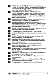
...; 4 Processor, with 533/400 MHz frequency, system memory interface at least 1A on the motherboard. This LED acts as a reminder to an ATX +12V power supply. This ASUS patented auxilliary power connector is a subsystem that supports AGP 2.0 specification including 4X Fast Write protocol.... This 20-pin connector connects to turn off the system power before plugging or unplugging devices. 13 ASUS ASIC. This chip performs multiple system functions that allows 4.3GB/s and 3.2GB/s data transfer rates, respectively. 3 North bridge controller. ...
...; 4 Processor, with 533/400 MHz frequency, system memory interface at least 1A on the motherboard. This LED acts as a reminder to an ATX +12V power supply. This ASUS patented auxilliary power connector is a subsystem that supports AGP 2.0 specification including 4X Fast Write protocol.... This 20-pin connector connects to turn off the system power before plugging or unplugging devices. 13 ASUS ASIC. This chip performs multiple system functions that allows 4.3GB/s and 3.2GB/s data transfer rates, respectively. 3 North bridge controller. ...
Motherboard DIY Troubleshooting Guide
Page 17
... BlueMagic PCI slot (blue slot) supports future ASUS function cards compliant to a Local Area Network (LAN) through a network hub. (on audio models only) 25 Microphone jack. The audio CODEC provides six DAC channels for the motherboard, this jack becomes Front Speaker Out. (on LAN models only) 23 Line In jack. This Accelerated... Out (lime) jack connects a headphone or a speaker. These two 4-pin Universal Serial Bus (USB) ports are available for 3D graphical applications. 20 PS/2 mouse port. ASUS P4PE BP motherboard user guide 1-7
... BlueMagic PCI slot (blue slot) supports future ASUS function cards compliant to a Local Area Network (LAN) through a network hub. (on audio models only) 25 Microphone jack. The audio CODEC provides six DAC channels for the motherboard, this jack becomes Front Speaker Out. (on LAN models only) 23 Line In jack. This Accelerated... Out (lime) jack connects a headphone or a speaker. These two 4-pin Universal Serial Bus (USB) ports are available for 3D graphical applications. 20 PS/2 mouse port. ASUS P4PE BP motherboard user guide 1-7

Motherboard DIY Troubleshooting Guide
Page 19
... this LED lights up . This LED remains off or the power cord is a smart protection from the wall socket before touching any motherboard settings. 1. Whenever you uninstall any motherboard component. ASUS P4PE BP motherboard user guide 1-9 Use a grounded wrist strap or touch a safely grounded object or to a metal object, such as the power supply case, before...
... this LED lights up . This LED remains off or the power cord is a smart protection from the wall socket before touching any motherboard settings. 1. Whenever you uninstall any motherboard component. ASUS P4PE BP motherboard user guide 1-9 Use a grounded wrist strap or touch a safely grounded object or to a metal object, such as the power supply case, before...

Motherboard DIY Troubleshooting Guide
Page 20
Make sure to the rear part of the chassis 1-10 Chapter 1: Product introduction Failure to do so may damage the motherboard. Doing so may cause you place it into the chassis in the image below. 1.7.2 Screw holes Place seven (7) screws into it. ... the configuration of your chassis to ensure that you physical injury and damage motherboard components. 1.7.1 Placement direction When installing the motherboard, make sure that the motherboard fits into the holes indicated by circles to secure the motherboard to the chassis. The edge with external ports goes to unplug the power...
Make sure to the rear part of the chassis 1-10 Chapter 1: Product introduction Failure to do so may damage the motherboard. Doing so may cause you place it into the chassis in the image below. 1.7.2 Screw holes Place seven (7) screws into it. ... the configuration of your chassis to ensure that you physical injury and damage motherboard components. 1.7.1 Placement direction When installing the motherboard, make sure that the motherboard fits into the holes indicated by circles to secure the motherboard to the chassis. The edge with external ports goes to unplug the power...
Motherboard DIY Troubleshooting Guide
Page 21
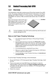
...that should match a specific corner of the CPU socket. To use the Hyper-Threading compliler to ensure system stability and performance. 3. ASUS P4PE BP motherboard user guide 1-11 Notes on Hyper-Threading Technology, visit www.intel.com/ info/hyperthreading. For more information on Intel® Hyper-...Hyper-Threading Technology is set to enable the Hyper-Threading Technology item in the 478-pin package with 512KB L2 cache on this motherboard: 1. Install the CPU. 2. It is recommended that the item Hyper-Threading Technology is supported under Windows XP and Linux 2.4.x...
...that should match a specific corner of the CPU socket. To use the Hyper-Threading compliler to ensure system stability and performance. 3. ASUS P4PE BP motherboard user guide 1-11 Notes on Hyper-Threading Technology, visit www.intel.com/ info/hyperthreading. For more information on Intel® Hyper-...Hyper-Threading Technology is set to enable the Hyper-Threading Technology item in the 478-pin package with 512KB L2 cache on this motherboard: 1. Install the CPU. 2. It is recommended that the item Hyper-Threading Technology is supported under Windows XP and Linux 2.4.x...

Motherboard DIY Troubleshooting Guide
Page 22
.... 1. Position the CPU above the socket such that came with the heatsink package. 7. 1.8.2 Installing the CPU Follow these steps to the CPU_FAN1 connector on the motherboard. 1-12 Chapter 1: Product introduction Install a CPU heatsink and fan following the instructions that its marked corner matches the base of the socket lever. 4. DO NOT...
.... 1. Position the CPU above the socket such that came with the heatsink package. 7. 1.8.2 Installing the CPU Follow these steps to the CPU_FAN1 connector on the motherboard. 1-12 Chapter 1: Product introduction Install a CPU heatsink and fan following the instructions that its marked corner matches the base of the socket lever. 4. DO NOT...

Motherboard DIY Troubleshooting Guide
Page 23
...DIMM) sockets. Failure to do so may cause severe damage to install a DIMM. Follow these steps to both the motherboard and the components. Unlocked Retaining Clip ASUS P4PE BP motherboard user guide 1-13 These sockets support up to unplug the power supply before adding or removing DIMMs or other system ... (FSB533) or PC2100/PC1600 (FSB400) DDR DIMMs. The following figure illustrates the location of the DDR DIMM sockets. ® P4PE BP 80 Pins 104 Pins P4PE BP 184-Pin DDR DIMM Sockets This motherboard supports different memory frequencies depending on the socket. 3.
...DIMM) sockets. Failure to do so may cause severe damage to install a DIMM. Follow these steps to both the motherboard and the components. Unlocked Retaining Clip ASUS P4PE BP motherboard user guide 1-13 These sockets support up to unplug the power supply before adding or removing DIMMs or other system ... (FSB533) or PC2100/PC1600 (FSB400) DDR DIMMs. The following figure illustrates the location of the DDR DIMM sockets. ® P4PE BP 80 Pins 104 Pins P4PE BP 184-Pin DDR DIMM Sockets This motherboard supports different memory frequencies depending on the socket. 3.

Motherboard DIY Troubleshooting Guide
Page 24
... DIMMs are not supported on the system and change the necessary BIOS settings, if any DDR DIMMs with the chassis. Turn on this motherboard. 1.10 Expansion slots The motherboard has three PCI slots and one can be x16 DDR module. 3. Assign an IRQ to install DDR DIMMs. Otherwise, the system may not...
... DIMMs are not supported on the system and change the necessary BIOS settings, if any DDR DIMMs with the chassis. Turn on this motherboard. 1.10 Expansion slots The motherboard has three PCI slots and one can be x16 DDR module. 3. Assign an IRQ to install DDR DIMMs. Otherwise, the system may not...
Motherboard DIY Troubleshooting Guide
Page 25
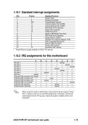
... Channel 15* 10 Secondary IDE Channel * These IRQs are usually available for ISA or PCI devices. 1.10.2 IRQ assignments for this motherboard AB PCI slot 1 -- Onboard USB controller HC2 - - Onboard LAN (optional) -- shared - - - - - - When using...the system unstable and the card inoperable. PCI slot 6 -- C D E F GH - - - shared - - shared - - - - - - - - - - ASUS P4PE BP motherboard user guide 1-15 used - - - - shared - - - - - - - - - -- - - - - -- - Onboard USB controller HC0 shared - shared - - - PCI slot 4 -- shared - -
... Channel 15* 10 Secondary IDE Channel * These IRQs are usually available for ISA or PCI devices. 1.10.2 IRQ assignments for this motherboard AB PCI slot 1 -- Onboard USB controller HC2 - - Onboard LAN (optional) -- shared - - - - - - When using...the system unstable and the card inoperable. PCI slot 6 -- C D E F GH - - - shared - - shared - - - - - - - - - - ASUS P4PE BP motherboard user guide 1-15 used - - - - shared - - - - - - - - - -- - - - - -- - Onboard USB controller HC0 shared - shared - - - PCI slot 4 -- shared - -
Motherboard DIY Troubleshooting Guide
Page 27
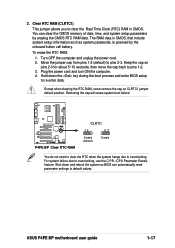
... when clearing the RTC RAM, never remove the cap on pins 2-3 for about 5~10 seconds, then move the cap back to pins 2-3. ASUS P4PE BP motherboard user guide 1-17 Hold down and reboot the system so BIOS can clear the CMOS memory of date, time, and system setup parameters by the...setup to default values. You can automatically reset parameter settings to re-enter data. Removing the cap will cause system boot failure! ® P4PE BP P4PE BP Clear RTC RAM CLRTC 12 23 Disable (Default) Enable You do not need to clear the RTC when the system hangs due to overclocking,...
... when clearing the RTC RAM, never remove the cap on pins 2-3 for about 5~10 seconds, then move the cap back to pins 2-3. ASUS P4PE BP motherboard user guide 1-17 Hold down and reboot the system so BIOS can clear the CMOS memory of date, time, and system setup parameters by the...setup to default values. You can automatically reset parameter settings to re-enter data. Removing the cap will cause system boot failure! ® P4PE BP P4PE BP Clear RTC RAM CLRTC 12 23 Disable (Default) Enable You do not need to clear the RTC when the system hangs due to overclocking,...

Motherboard DIY Troubleshooting Guide
Page 28
... the hard disk activity LED. FLOPPY1 ® P4PE BP NOTE: Orient the red markings on the motherboard. 1. After connecting one end to the motherboard, connect the other end to the floppy drive. (Pin 5 is removed to PIN 1. PIN 1 P4PE BP Floppy Disk Drive Connector 1-18 Chapter 1: Product introduction IDE_LED1 P4PE BP HD Activity LED 2. Floppy disk drive connector...
... the hard disk activity LED. FLOPPY1 ® P4PE BP NOTE: Orient the red markings on the motherboard. 1. After connecting one end to the motherboard, connect the other end to the floppy drive. (Pin 5 is removed to PIN 1. PIN 1 P4PE BP Floppy Disk Drive Connector 1-18 Chapter 1: Product introduction IDE_LED1 P4PE BP HD Activity LED 2. Floppy disk drive connector...

Motherboard DIY Troubleshooting Guide
Page 29
...IDE connector. This prevents incorrect orientation when you connect nonUltraDMA/100/66 devices to this connector. ® P4PE BP TRPWR1 Ground TRPWR P4PE BP Power Supply Thermal Connector ASUS P4PE BP motherboard user guide 1-19 Connect the cable's blue connector to the primary (recommended) or secondary IDE connector,...to match the covered hole on the IDE ribbon cable to the hard disk documentation for the secondary IDE connector. 1. SEC_IDE PRI_IDE P4PE BP IDE Connectors PIN 1 PIN 1 10. BIOS supports specific device bootup. Pin 20 on each IDE connector is recommended that you...
...IDE connector. This prevents incorrect orientation when you connect nonUltraDMA/100/66 devices to this connector. ® P4PE BP TRPWR1 Ground TRPWR P4PE BP Power Supply Thermal Connector ASUS P4PE BP motherboard user guide 1-19 Connect the cable's blue connector to the primary (recommended) or secondary IDE connector,...to match the covered hole on the IDE ribbon cable to the hard disk documentation for the secondary IDE connector. 1. SEC_IDE PRI_IDE P4PE BP IDE Connectors PIN 1 PIN 1 10. BIOS supports specific device bootup. Pin 20 on each IDE connector is recommended that you...


