
Motherboard DIY Troubleshooting Guide
Page 14
... two serial ports. 7 Floppy Disk connector. The chipset supports a high-performance floppy disk controller for the Intel® Pentium® 4 processor, a memory controller and an integrated graphics interface. 4 DDR DIMM Sockets. These two 184-pin DIMM sockets support up to four Ultra DMA 100/66, PIO Modes 3 & 4 IDE devices. These dual-channel bus master IDE connectors support up to an ATX 12V power supply. This connector connects the provided ribbon cable for two PCI Slots. 11 ASUS ASIC. This power connector connects the 4-pin 12V plug from the ATX 12V power supply. 2 CPU...
... two serial ports. 7 Floppy Disk connector. The chipset supports a high-performance floppy disk controller for the Intel® Pentium® 4 processor, a memory controller and an integrated graphics interface. 4 DDR DIMM Sockets. These two 184-pin DIMM sockets support up to four Ultra DMA 100/66, PIO Modes 3 & 4 IDE devices. These dual-channel bus master IDE connectors support up to an ATX 12V power supply. This connector connects the provided ribbon cable for two PCI Slots. 11 ASUS ASIC. This power connector connects the 4-pin 12V plug from the ATX 12V power supply. 2 CPU...
Motherboard DIY Troubleshooting Guide
Page 15
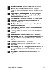
...-bit PCI 2.2 expansion slots support bus master PCI cards like SCSI and LAN cards with 133MB/s maximum output. 14 Single-Chip Fast Ethernet controller. This 25-pin port connects a parallel printer, a scanner, or other serial devices. 24 USB 2.0 ports. This port connects a VGA monitor. 23 Serial port. This purple 6-pin connector is AC '97 compliant. 13 PCI slots. This Line In (light blue) jack connects a tape player or other audio sources. 19 Line Out jack. ASUS P4BGL-MX Motherboard 1-5 12 Audio/Modem CODEC. The RealTek 8101L PCI LAN...
...-bit PCI 2.2 expansion slots support bus master PCI cards like SCSI and LAN cards with 133MB/s maximum output. 14 Single-Chip Fast Ethernet controller. This 25-pin port connects a parallel printer, a scanner, or other serial devices. 24 USB 2.0 ports. This port connects a VGA monitor. 23 Serial port. This purple 6-pin connector is AC '97 compliant. 13 PCI slots. This Line In (light blue) jack connects a tape player or other audio sources. 19 Line Out jack. ASUS P4BGL-MX Motherboard 1-5 12 Audio/Modem CODEC. The RealTek 8101L PCI LAN...

Motherboard DIY Troubleshooting Guide
Page 18
... Pins P4BGL-MX 104 Pins P4BGL-MX 184-Pin DDR DIMM Sockets 1. Turn on BIOS setup. 2. Install the software drivers for information on the system and change the necessary BIOS settings, if any. 1.8 System memory The motherboard has two Double Data Rate (DDR) DIMM sockets that supports up to avoid damaging the DIMM. 1.9 Expansion slots The P4BGL-MX motherboard has three (3) expansion slots. A DDR DIMM is keyed with a notch so that they support. 1.9.1 Configuring an expansion card After physically installing the...
... Pins P4BGL-MX 104 Pins P4BGL-MX 184-Pin DDR DIMM Sockets 1. Turn on BIOS setup. 2. Install the software drivers for information on the system and change the necessary BIOS settings, if any. 1.8 System memory The motherboard has two Double Data Rate (DDR) DIMM sockets that supports up to avoid damaging the DIMM. 1.9 Expansion slots The P4BGL-MX motherboard has three (3) expansion slots. A DDR DIMM is keyed with a notch so that they support. 1.9.1 Configuring an expansion card After physically installing the...
Motherboard DIY Troubleshooting Guide
Page 19
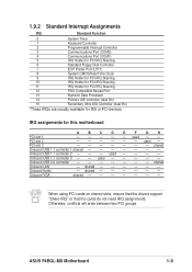
...- ASUS P4BGL-MX Motherboard 1-9 Onboard USB 2.0 controller shared Onboard LAN - used - - Onboard VGA shared When using PCI cards on shared slots, ensure that the drivers support "Share IRQ" or that the cards do not need IRQ assignments. 1.9.2 Standard Interrupt Assignments IRQ Standard Function 0 System Timer 1 Keyboard Controller 2 Programmable Interrupt Controller 3 Communications Port (COM2) 4 Communications Port (COM1) 5 IRQ Holder for PCI IRQ Steering 6 Standard Floppy Disk Controller 7 ECP Printer Port (LPT1) 8 System CMOS/Real Time Clock 9 IRQ...
...- ASUS P4BGL-MX Motherboard 1-9 Onboard USB 2.0 controller shared Onboard LAN - used - - Onboard VGA shared When using PCI cards on shared slots, ensure that the drivers support "Share IRQ" or that the cards do not need IRQ assignments. 1.9.2 Standard Interrupt Assignments IRQ Standard Function 0 System Timer 1 Keyboard Controller 2 Programmable Interrupt Controller 3 Communications Port (COM2) 4 Communications Port (COM1) 5 IRQ Holder for PCI IRQ Steering 6 Standard Floppy Disk Controller 7 ECP Printer Port (LPT1) 8 System CMOS/Real Time Clock 9 IRQ...
Motherboard DIY Troubleshooting Guide
Page 21
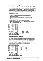
... power cord. 2. Hold down the key during the boot process and enter BIOS setup to wake up feature. To erase the RTC RAM: 1. Plug the power cord and turn ON the computer. 6. Set this jumper to pins 2-3 (+5VSB) if you to clear the Real Time Clock (RTC) RAM in CMOS, that can clear the CMOS memory of date, time, and system setup parameters by the onboard button cell battery. The RAM data in CMOS. P4BGL-MX KBPWR1 2 1 +5V (Default) 3 2 +5VSB (Default) P4BGL-MX Keyboard Power Setting ASUS P4BGL-MX Motherboard...
... power cord. 2. Hold down the key during the boot process and enter BIOS setup to wake up feature. To erase the RTC RAM: 1. Plug the power cord and turn ON the computer. 6. Set this jumper to pins 2-3 (+5VSB) if you to clear the Real Time Clock (RTC) RAM in CMOS, that can clear the CMOS memory of date, time, and system setup parameters by the onboard button cell battery. The RAM data in CMOS. P4BGL-MX KBPWR1 2 1 +5V (Default) 3 2 +5VSB (Default) P4BGL-MX Keyboard Power Setting ASUS P4BGL-MX Motherboard...

Motherboard DIY Troubleshooting Guide
Page 22
... jumper accordingly. You may configure two hard disks to PIN 1. Pin 20 on the UltraDMA cable connector. For UltraDMA100/66 IDE devices, use an 80-conductor IDE cable. 1.11 Connectors This section describes and illustrates the connectors on the IDE ribbon cable to be both master devices with two ribbon cables - If you connect the cables. P4BGL-MX P4BGL-MX IDE Connectors SEC_IDE PRI_IDE NOTE: Orient the red markings (usually zigzag) on the motherboard. 1. BIOS supports specific device bootup. PIN 1 1-12 Chapter 1: Motherboard Information Connect...
... jumper accordingly. You may configure two hard disks to PIN 1. Pin 20 on the UltraDMA cable connector. For UltraDMA100/66 IDE devices, use an 80-conductor IDE cable. 1.11 Connectors This section describes and illustrates the connectors on the IDE ribbon cable to be both master devices with two ribbon cables - If you connect the cables. P4BGL-MX P4BGL-MX IDE Connectors SEC_IDE PRI_IDE NOTE: Orient the red markings (usually zigzag) on the motherboard. 1. BIOS supports specific device bootup. PIN 1 1-12 Chapter 1: Motherboard Information Connect...

Motherboard DIY Troubleshooting Guide
Page 28
... Ground Ground Speaker +5 V MLED ExtSMI# Ground PWR Ground Reset Ground P4BGL-MX Message LED SMI Lead Reset SW ATX Power Switch* P4BGL-MX System Panel Connectors * Requires an ATX power supply. • System Power LED Lead (2-pin PLED) This 2-pin connector connects to the primary or secondary IDE slots. The LED lights up on the system power. • Keyboard Lock Lead (2-pin KEYLOCK) This 2-pin connector connects to a chassis-mounted switch to allow the use of the disk drives connected to the system power LED. Hard disk connector (2-pin HDDLED) This 2-pin connector connects to...
... Ground Ground Speaker +5 V MLED ExtSMI# Ground PWR Ground Reset Ground P4BGL-MX Message LED SMI Lead Reset SW ATX Power Switch* P4BGL-MX System Panel Connectors * Requires an ATX power supply. • System Power LED Lead (2-pin PLED) This 2-pin connector connects to the primary or secondary IDE slots. The LED lights up on the system power. • Keyboard Lock Lead (2-pin KEYLOCK) This 2-pin connector connects to a chassis-mounted switch to allow the use of the disk drives connected to the system power LED. Hard disk connector (2-pin HDDLED) This 2-pin connector connects to...
Motherboard DIY Troubleshooting Guide
Page 32
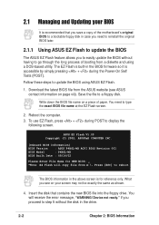
... BIOS Model : P4BGL-MX BIOS Built Date : 09/16/02 Please Enter File Name for NEW BIOS: _ *Note: EZ Flash will receive the error message, "WARNING! Device not ready." Save the file to update the BIOS using a DOS-based utility. Insert the disk that you save a copy of the motherboard's original BIOS to type the exact BIOS file name at the EZ Flash screen. 2. Download the latest BIOS file from the ASUS website (see on your BIOS It is accessible...
... BIOS Model : P4BGL-MX BIOS Built Date : 09/16/02 Please Enter File Name for NEW BIOS: _ *Note: EZ Flash will receive the error message, "WARNING! Device not ready." Save the file to update the BIOS using a DOS-based utility. Insert the disk that you save a copy of the motherboard's original BIOS to type the exact BIOS file name at the EZ Flash screen. 2. Download the latest BIOS file from the ASUS website (see on your BIOS It is accessible...

Motherboard DIY Troubleshooting Guide
Page 34
... the BIOS version of your motherboard, check the last four numbers of your screen may be programmed by the Flash Memory Writer utility. 2-4 Chapter 2: BIOS Information It does not work with certain memory drivers that updates the BIOS by the ACPI BIOS and therefore, cannot be loaded when you see on the upper left-hand corner of the code displayed on your screen during bootup. What you boot from the floppy disk...
... the BIOS version of your motherboard, check the last four numbers of your screen may be programmed by the Flash Memory Writer utility. 2-4 Chapter 2: BIOS Information It does not work with certain memory drivers that updates the BIOS by the ACPI BIOS and therefore, cannot be loaded when you see on the upper left-hand corner of the code displayed on your screen during bootup. What you boot from the floppy disk...
Motherboard DIY Troubleshooting Guide
Page 37
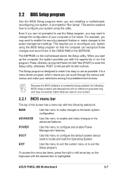
... the CMOS RAM of the EEPROM. ASUS P4BGL-MX Motherboard 2-7 For example, you can recognize these changes and record them in the future. The EEPROM on the keyboard until the desired item is a menu-driven program, which means you may want to enable the security password feature or make changes to enter the Setup utility, otherwise, POST continues with its test routines. It is highlighted. POWER Use this menu...
... the CMOS RAM of the EEPROM. ASUS P4BGL-MX Motherboard 2-7 For example, you can recognize these changes and record them in the future. The EEPROM on the keyboard until the desired item is a menu-driven program, which means you may want to enable the security password feature or make changes to enter the Setup utility, otherwise, POST continues with its test routines. It is highlighted. POWER Use this menu...

Motherboard DIY Troubleshooting Guide
Page 40
... not case sensitive, meaning, passwords typed in a password then press . You can type up to 2099). This password allows full access to [Enabled]. Passwords are accepted. Forgot the password? Re-install the battery after about passwords The BIOS Setup program allows you did , the Supervisor password is required to support older Japanese floppy drives. Legacy Diskette A [1.44M, 3.5 in .] Floppy 3 Mode Support [Disabled] This is required to enter the BIOS Setup program and to gain full access to the configuration...
... not case sensitive, meaning, passwords typed in a password then press . You can type up to 2099). This password allows full access to [Enabled]. Passwords are accepted. Forgot the password? Re-install the battery after about passwords The BIOS Setup program allows you did , the Supervisor password is required to support older Japanese floppy drives. Legacy Diskette A [1.44M, 3.5 in .] Floppy 3 Mode Support [Disabled] This is required to enter the BIOS Setup program and to gain full access to the configuration...
Motherboard DIY Troubleshooting Guide
Page 42
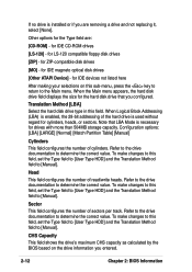
... not replacing it, select [None]. for cylinders, heads, or sectors. When the Main menu appears, the hard disk drive field displays the size for IDE CD-ROM drives [LS-120] - To make changes to this field, set the Type field to [User Type HDD] and the Translation Method field to the Main menu. If no drive is installed or if you are : [CD-ROM] - for the hard disk drive that LBA Mode is necessary for IDE devices not listed...
... not replacing it, select [None]. for cylinders, heads, or sectors. When the Main menu appears, the hard disk drive field displays the size for IDE CD-ROM drives [LS-120] - To make changes to this field, set the Type field to [User Type HDD] and the Translation Method field to the Main menu. If no drive is installed or if you are : [CD-ROM] - for the hard disk drive that LBA Mode is necessary for IDE devices not listed...

Motherboard DIY Troubleshooting Guide
Page 43
... the BIOS based on the drive information you to enable or disable the S.M.A.R.T. (Self-Monitoring, Analysis and Reporting Technology) system that utilizes internal hard disk drive monitoring technology. To make changes to [User Type HDD]. This parameter is automatically configured, the set a PIO (Programmed Input/Output) mode for compatible IDE devices. Set to [Disabled] to the highest number that the drive supports. You may also manually configure this field, set the Type field to this field is normally disabled because the resources used...
... the BIOS based on the drive information you to enable or disable the S.M.A.R.T. (Self-Monitoring, Analysis and Reporting Technology) system that utilizes internal hard disk drive monitoring technology. To make changes to [User Type HDD]. This parameter is automatically configured, the set a PIO (Programmed Input/Output) mode for compatible IDE devices. Set to [Disabled] to the highest number that the drive supports. You may also manually configure this field, set the Type field to this field is normally disabled because the resources used...

Motherboard DIY Troubleshooting Guide
Page 44
... Menu This motherboard supports overclocking to 30 characters per second. The bus frequency (external frequency) multiplied by the bus multiple equals the CPU speed. 2-14 Chapter 2: BIOS Information CPU External Frequency (MHz) This feature tells the clock generator what frequency to send to activate the Number Lock function upon system boot. To adjust CPU Speed and Memory Frequency, enter the BIOS Setup Utility and select the Advanced Menu. Configuration options: [Off] [On] Keyboard Auto-Repeat Rate [6/Sec] This controls the speed...
... Menu This motherboard supports overclocking to 30 characters per second. The bus frequency (external frequency) multiplied by the bus multiple equals the CPU speed. 2-14 Chapter 2: BIOS Information CPU External Frequency (MHz) This feature tells the clock generator what frequency to send to activate the Number Lock function upon system boot. To adjust CPU Speed and Memory Frequency, enter the BIOS Setup Utility and select the Advanced Menu. Configuration options: [Off] [On] Keyboard Auto-Repeat Rate [6/Sec] This controls the speed...

Motherboard DIY Troubleshooting Guide
Page 45
...are using OS/2 operating systems with installed DRAM of [Auto] allows the system to [Enabled]. If not detected, the USB controller legacy mode is enabled. Configuration options: [Disabled] [Enabled] BIOS Update [Enabled] This field functions as an update loader integrated into the BIOS to supply the processor with respect to the system frequency. Otherwise, IRQ12 can be in synchronous or asynchronous mode with the required data. Otherwise, leave to the CPU Frequency (MHz). Configuration options: [Disabled] [Enabled] ASUS P4BGL-MX Motherboard 2-15 Memory Frequency [Auto] This...
...are using OS/2 operating systems with installed DRAM of [Auto] allows the system to [Enabled]. If not detected, the USB controller legacy mode is enabled. Configuration options: [Disabled] [Enabled] BIOS Update [Enabled] This field functions as an update loader integrated into the BIOS to supply the processor with respect to the system frequency. Otherwise, IRQ12 can be in synchronous or asynchronous mode with the required data. Otherwise, leave to the CPU Frequency (MHz). Configuration options: [Disabled] [Enabled] ASUS P4BGL-MX Motherboard 2-15 Memory Frequency [Auto] This...

Motherboard DIY Troubleshooting Guide
Page 47
...] Video Memory Cache Mode [UC] USWC (uncacheable, speculative write combining) is accessing 8-bit ISA cards. Configuration options: [Low] [Medium] [High] [Maximum] ASUS P4BGL-MX Motherboard 2-17 This process normally consumes about 50-60 PCI clocks without PCI delayed transaction. Configuration options: [Both] [Primary] [Secondary] [Disabled] USB 2.0 HS Reference Voltage [Medium] This item controls the USB 2.0 high-speed drive strength reference voltage. Configuration options: [Enabled] [Disabled] Graphics Aperture Size [128MB] This feature allows you to enable either the primary IDE...
...] Video Memory Cache Mode [UC] USWC (uncacheable, speculative write combining) is accessing 8-bit ISA cards. Configuration options: [Low] [Medium] [High] [Maximum] ASUS P4BGL-MX Motherboard 2-17 This process normally consumes about 50-60 PCI clocks without PCI delayed transaction. Configuration options: [Both] [Primary] [Secondary] [Disabled] USB 2.0 HS Reference Voltage [Medium] This item controls the USB 2.0 high-speed drive strength reference voltage. Configuration options: [Enabled] [Disabled] Graphics Aperture Size [128MB] This feature allows you to enable either the primary IDE...
Motherboard DIY Troubleshooting Guide
Page 49
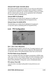
... the default setting [32] for the MIDI port. If you are using any audio device. If an audio device is detected, the onboard audio controller is disabled. Configuration options: [Auto] [NA] [3] [4] [5] [7] [9] [10] [11] [12] [14] [15] PCI/VGA Palette Snoop [Disabled] Some non-standard VGA cards, like graphics accelerators or MPEG video cards, may not show colors properly. Configuration options: [Disabled] [Enabled] PCI Latency Timer [32] Leave this field to select the I /O address for each PCI slot. Onboard AC97 Audio Controller [Auto] [Auto] allows the BIOS...
... the default setting [32] for the MIDI port. If you are using any audio device. If an audio device is detected, the onboard audio controller is disabled. Configuration options: [Auto] [NA] [3] [4] [5] [7] [9] [10] [11] [12] [14] [15] PCI/VGA Palette Snoop [Disabled] Some non-standard VGA cards, like graphics accelerators or MPEG video cards, may not show colors properly. Configuration options: [Disabled] [Enabled] PCI Latency Timer [32] Leave this field to select the I /O address for each PCI slot. Onboard AC97 Audio Controller [Auto] [Auto] allows the BIOS...

Motherboard DIY Troubleshooting Guide
Page 50
Configuration options: [PCI VGA Card] [Onboard VGA] Onboard LAN Controller [Enabled] This field allows you to select primary graphics card or onboard VGA as the primary display BIOS. Configuration options: [Disabled] [Enabled] Onboard LAN Boot ROM [Disabled] This field allows you to turn on or off the USB 2.0 controller. Configuration options: [No/ICU] [Yes] 2-20 Chapter 2: BIOS Information This item appears only when onboard LAN exist. Set the IRQ field to [Yes] if you are NOT using the ISA Configuration Utility (ICU), and that requires a unique IRQ and you...
Configuration options: [PCI VGA Card] [Onboard VGA] Onboard LAN Controller [Enabled] This field allows you to select primary graphics card or onboard VGA as the primary display BIOS. Configuration options: [Disabled] [Enabled] Onboard LAN Boot ROM [Disabled] This field allows you to turn on or off the USB 2.0 controller. Configuration options: [No/ICU] [Yes] 2-20 Chapter 2: BIOS Information This item appears only when onboard LAN exist. Set the IRQ field to [Yes] if you are NOT using the ISA Configuration Utility (ICU), and that requires a unique IRQ and you...

Motherboard DIY Troubleshooting Guide
Page 60
... motherboard settings and hardware options vary, use the setup procedures presented in this motherboard. If Autorun is the contact information for general reference only. The menu lists the drivers and utilities that enhance the motherboard features. Simply click on your hardware. Also, included is enabled in the support CD to your CD-ROM drive. Refer to display the menu. The contents of your screen. Visit the ASUS website for updates...
... motherboard settings and hardware options vary, use the setup procedures presented in this motherboard. If Autorun is the contact information for general reference only. The menu lists the drivers and utilities that enhance the motherboard features. Simply click on your hardware. Also, included is enabled in the support CD to your CD-ROM drive. Refer to display the menu. The contents of your screen. Visit the ASUS website for updates...
Motherboard DIY Troubleshooting Guide
Page 61
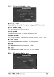
3.2.2 Software Installation menu ASUS PC Probe Install utility that can monitor Fan, Speed, Voltage, and CPU temperature. E-Color 3Deep This item installs application to download and update motherboard BIOS. PC-cillin This item installs the Trend PC-cillin 2002 anti-virus software. 3.2.3 Drivers installation menu ASUS P4BGL-MX Motherboard 3-3 Acrobat Reader This installs software for viewing files in Portable Document Format (PDF). ASUS Update Installs utility to optimize 3D graphics output. ASUS Screen Saver This item installs the ASUS screen saver. DirectX This item installs the ...
3.2.2 Software Installation menu ASUS PC Probe Install utility that can monitor Fan, Speed, Voltage, and CPU temperature. E-Color 3Deep This item installs application to download and update motherboard BIOS. PC-cillin This item installs the Trend PC-cillin 2002 anti-virus software. 3.2.3 Drivers installation menu ASUS P4BGL-MX Motherboard 3-3 Acrobat Reader This installs software for viewing files in Portable Document Format (PDF). ASUS Update Installs utility to optimize 3D graphics output. ASUS Screen Saver This item installs the ASUS screen saver. DirectX This item installs the ...


