Motherboard DIY Troubleshooting Guide
Page 3
... guide vii Conventions used in this guide vii Where to update the BIOS 2-4 Updating BIOS procedures 2-5 2.2 BIOS Setup Program 2-7 2.2.1 BIOS menu bar 2-7 2.2.2 Legend bar 2-8 iii BIOS Information 2-1 2.1 Managing and updating your BIOS 2-2 2.1.1 Using ASUS EZ FLASH to update the BIOS 2-2 2.1.2 Using ASUS AFLASH to find more information vii ASUS contact information vii Specifications summary ix Chapter 1 - Motherboard Info 1-1 1.1 Welcome 1-2 1.2 Package...
... guide vii Conventions used in this guide vii Where to update the BIOS 2-4 Updating BIOS procedures 2-5 2.2 BIOS Setup Program 2-7 2.2.1 BIOS menu bar 2-7 2.2.2 Legend bar 2-8 iii BIOS Information 2-1 2.1 Managing and updating your BIOS 2-2 2.1.1 Using ASUS EZ FLASH to update the BIOS 2-2 2.1.2 Using ASUS AFLASH to find more information vii ASUS contact information vii Specifications summary ix Chapter 1 - Motherboard Info 1-1 1.1 Welcome 1-2 1.2 Package...

Motherboard DIY Troubleshooting Guide
Page 9
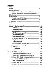
P4BGL-MX specifications summary CPU Chipset Front Side Bus (FSB) Memory Expansion slots IDE Audio LAN Special Features Back Panel I/O Ports Internal I/O Connectors Socket 478 ofr Intel ... PC2100/1600 non-ECC DDR SDRAM 3 x PCI 2 x UltraDMA 100/66 RealTek 2-channel CODEC RealTek 8101L PCI LAN integrated 10/100Mbps Fast Ethernet Power Loss Restart ASUS JumperFree BIOS write protections CPU Throttle 1 x Parallel 1 x Serial 1 x VGA 1 x PS/2 Keyboard 1 x PS/2 Mouse 4 x USB 2.0 1 x RJ-45 Port CPU/Chassis FAN connector 20 pin ATX power connector...
P4BGL-MX specifications summary CPU Chipset Front Side Bus (FSB) Memory Expansion slots IDE Audio LAN Special Features Back Panel I/O Ports Internal I/O Connectors Socket 478 ofr Intel ... PC2100/1600 non-ECC DDR SDRAM 3 x PCI 2 x UltraDMA 100/66 RealTek 2-channel CODEC RealTek 8101L PCI LAN integrated 10/100Mbps Fast Ethernet Power Loss Restart ASUS JumperFree BIOS write protections CPU Throttle 1 x Parallel 1 x Serial 1 x VGA 1 x PS/2 Keyboard 1 x PS/2 Mouse 4 x USB 2.0 1 x RJ-45 Port CPU/Chassis FAN connector 20 pin ATX power connector...
Motherboard DIY Troubleshooting Guide
Page 10
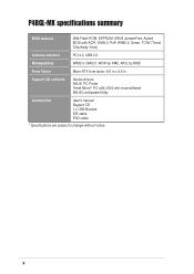
x P4BGL-MX specifications summary BIOS features 2Mb Flash ROM, EEPROM, ASUS JumperFree, Award BIOS with ACPI, DMI2.0, PnP, WfM2.0, Green, TCAV (Trend Chip Away Virus) Industry standard PCI 2.2, USB 2.0. Manageability WfM2.0, DMI2.0, WOR by PME, WOL by BME Form Factor Micro-ATX form factor: 8.6 in x 9.6 in Support CD contents Device drivers ASUS PC Probe Trend Microtm PC-cillin 2002 anti-virus software ASUS LiveUpdate Utility Accessories User's manual Support CD 1 x USB Bracket IDE cable FDD cable * Specifications are subject to change without notice.
x P4BGL-MX specifications summary BIOS features 2Mb Flash ROM, EEPROM, ASUS JumperFree, Award BIOS with ACPI, DMI2.0, PnP, WfM2.0, Green, TCAV (Trend Chip Away Virus) Industry standard PCI 2.2, USB 2.0. Manageability WfM2.0, DMI2.0, WOR by PME, WOL by BME Form Factor Micro-ATX form factor: 8.6 in x 9.6 in Support CD contents Device drivers ASUS PC Probe Trend Microtm PC-cillin 2002 anti-virus software ASUS LiveUpdate Utility Accessories User's manual Support CD 1 x USB Bracket IDE cable FDD cable * Specifications are subject to change without notice.

Motherboard DIY Troubleshooting Guide
Page 14
...and two serial ports. 7 Floppy Disk connector. This interface provides the commonly used Super I /O chipset. This 2Mb firmware contains the programmable BIOS program. 10 South bridge controller. A 478-pin surface mount, Zero Insertion Force (ZIF) socket for the floppy disk drive. This connector connects... AC'97 Interface, six Universal Serial Bus 2.0, two IDE Master/Slave controllers, the ITE 8708F Super I/O, Flash BIOS, and PCI bus for two PCI Slots. 11 ASUS ASIC. This chip performs multiple system functions that allows 3.2 GB/s data transfer rates. 3 NorthBridge Controller. This ...
...and two serial ports. 7 Floppy Disk connector. This interface provides the commonly used Super I /O chipset. This 2Mb firmware contains the programmable BIOS program. 10 South bridge controller. A 478-pin surface mount, Zero Insertion Force (ZIF) socket for the floppy disk drive. This connector connects... AC'97 Interface, six Universal Serial Bus 2.0, two IDE Master/Slave controllers, the ITE 8708F Super I/O, Flash BIOS, and PCI bus for two PCI Slots. 11 ASUS ASIC. This chip performs multiple system functions that allows 3.2 GB/s data transfer rates. 3 NorthBridge Controller. This ...

Motherboard DIY Troubleshooting Guide
Page 18
... describe the slots and the expansion cards that supports up to avoid damaging the DIMM. 1.9 Expansion slots The P4BGL-MX motherboard has three (3) expansion slots. Refer to the card. Turn on BIOS setup. 2. Assign an IRQ to the tables below. 3. See Chapter 2 for the expansion card. 1-8... Chapter 1: Motherboard Information DO NOT force a DIMM into a socket to 2GB non-ECC PC2100/1600 DDR. 80 Pins P4BGL-MX 104 Pins P4BGL-MX 184-Pin DDR DIMM Sockets 1....
... describe the slots and the expansion cards that supports up to avoid damaging the DIMM. 1.9 Expansion slots The P4BGL-MX motherboard has three (3) expansion slots. Refer to the card. Turn on BIOS setup. 2. Assign an IRQ to the tables below. 3. See Chapter 2 for the expansion card. 1-8... Chapter 1: Motherboard Information DO NOT force a DIMM into a socket to 2GB non-ECC PC2100/1600 DDR. 80 Pins P4BGL-MX 104 Pins P4BGL-MX 184-Pin DDR DIMM Sockets 1....
Motherboard DIY Troubleshooting Guide
Page 21
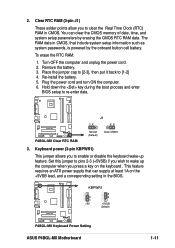
...CMOS 3. Set this jumper to pins 2-3 (+5VSB) if you wish to wake up feature. The RAM data in CMOS. P4BGL-MX KBPWR1 2 1 +5V (Default) 3 2 +5VSB (Default) P4BGL-MX Keyboard Power Setting ASUS P4BGL-MX Motherboard 1-11 To erase the RTC RAM: 1. Plug the power cord and turn ON the computer. 6. This feature requires an... the CMOS RTC RAM data. You can supply at least 1A on the keyboard . Hold down the key during the boot process and enter BIOS setup to [1-2] 4. Turn OFF the computer and unplug the power cord. 2. Keyboard power (3-pin KBPWR1) This jumper allows you to enable ...
...CMOS 3. Set this jumper to pins 2-3 (+5VSB) if you wish to wake up feature. The RAM data in CMOS. P4BGL-MX KBPWR1 2 1 +5V (Default) 3 2 +5VSB (Default) P4BGL-MX Keyboard Power Setting ASUS P4BGL-MX Motherboard 1-11 To erase the RTC RAM: 1. Plug the power cord and turn ON the computer. 6. This feature requires an... the CMOS RTC RAM data. You can supply at least 1A on the keyboard . Hold down the key during the boot process and enter BIOS setup to [1-2] 4. Turn OFF the computer and unplug the power cord. 2. Keyboard power (3-pin KBPWR1) This jumper allows you to enable ...

Motherboard DIY Troubleshooting Guide
Page 22
... you have more than two UltraDMA100/66 devices, purchase another for the secondary IDE connector. BIOS supports specific device bootup. one for the jumper settings. For UltraDMA100/66 IDE devices, use an 80-conductor IDE cable. P4BGL-MX P4BGL-MX IDE Connectors SEC_IDE PRI_IDE NOTE: Orient the red markings (usually zigzag) on the motherboard. 1. If...
... you have more than two UltraDMA100/66 devices, purchase another for the secondary IDE connector. BIOS supports specific device bootup. one for the jumper settings. For UltraDMA100/66 IDE devices, use an 80-conductor IDE cable. P4BGL-MX P4BGL-MX IDE Connectors SEC_IDE PRI_IDE NOTE: Orient the red markings (usually zigzag) on the motherboard. 1. If...
Motherboard DIY Troubleshooting Guide
Page 27
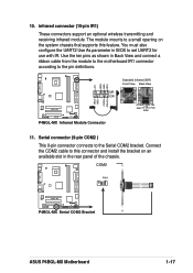
...Infrared (SIR) Front View Back View SIR CIR IRTX +5V GND (NC) IRRX P4BGL-MX Infrared Module Connector 11. Serial connector (9-pin COM2 ) This 9-pin connector connects to the pin definitions. COM2 PIN 1 P4BGL-MX P4BGL-MX Serial COM2 Bracket ASUS P4BGL-MX Motherboard 1-17 infrared connector (10-pin IR1) These connectors support an optional wireless ...to the motherboard IR1 connector according to the Serial COM2 bracket. The module mounts to a small opening on an available slot in BIOS to this connector and install the bracket on the system chassis that supports this feature.
...Infrared (SIR) Front View Back View SIR CIR IRTX +5V GND (NC) IRRX P4BGL-MX Infrared Module Connector 11. Serial connector (9-pin COM2 ) This 9-pin connector connects to the pin definitions. COM2 PIN 1 P4BGL-MX P4BGL-MX Serial COM2 Bracket ASUS P4BGL-MX Motherboard 1-17 infrared connector (10-pin IR1) These connectors support an optional wireless ...to the motherboard IR1 connector according to the Serial COM2 bracket. The module mounts to a small opening on an available slot in BIOS to this connector and install the bracket on the system chassis that supports this feature.

Motherboard DIY Troubleshooting Guide
Page 29
... connects to the case-mounted reset switch for more than 4 seconds turns the system OFF. ASUS P4BGL-MX Motherboard 1-19 Pressing the power switch turns the system between ON and SLEEP, or ON and SOFT OFF, depending on the BIOS or OS settings. • System Warning Speaker Lead (4-pin SPEAKER) This 4-pin connector connects...
... connects to the case-mounted reset switch for more than 4 seconds turns the system OFF. ASUS P4BGL-MX Motherboard 1-19 Pressing the power switch turns the system between ON and SLEEP, or ON and SOFT OFF, depending on the BIOS or OS settings. • System Warning Speaker Lead (4-pin SPEAKER) This 4-pin connector connects...
Motherboard DIY Troubleshooting Guide
Page 31
BIOS Information ASUS P4BGL-MX Motherboard 2-1 Chapter 2 This chapter gives information about the ASUS P4BGL-MX Binary Input/Output System (BIOS).This chapter includes updating the BIOS using the ASUS AFLASH BIOS that is bundled with the support CD.
BIOS Information ASUS P4BGL-MX Motherboard 2-1 Chapter 2 This chapter gives information about the ASUS P4BGL-MX Binary Input/Output System (BIOS).This chapter includes updating the BIOS using the ASUS AFLASH BIOS that is bundled with the support CD.
Motherboard DIY Troubleshooting Guide
Page 32
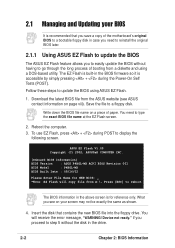
... is accessible by simply pressing + during POST to update the BIOS using a DOS-based utility. ASUS EZ Flash V1.00 Copyright (C) 2002, ASUSTeK COMPUTER INC. [Onboard BIOS Information] BIOS Version : ASUS P4BGL-MX ACPI BIOS Revision 001 BIOS Model : P4BGL-MX BIOS Built Date : 09/16/02 Please Enter File Name for NEW BIOS: _ *Note: EZ Flash will receive the error message, "WARNING...
... is accessible by simply pressing + during POST to update the BIOS using a DOS-based utility. ASUS EZ Flash V1.00 Copyright (C) 2002, ASUSTeK COMPUTER INC. [Onboard BIOS Information] BIOS Version : ASUS P4BGL-MX ACPI BIOS Revision 001 BIOS Model : P4BGL-MX BIOS Built Date : 09/16/02 Please Enter File Name for NEW BIOS: _ *Note: EZ Flash will receive the error message, "WARNING...
Motherboard DIY Troubleshooting Guide
Page 33
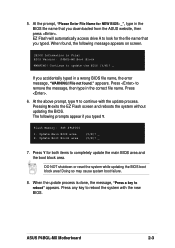
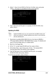
... appears on screen. [BIOS Information in the BIOS file name that you downloaded from the ASUS website, then press . Update Main BIOS area 2. Press to continue with the new BIOS. Update Boot Block area (Y/N)? _ (Y/N)? _ 7. At the above prompt, type Y to remove the message, then type in a wrong BIOS file name, the error message, "WARNING! ASUS P4BGL-MX Motherboard 2-3 Press...
... appears on screen. [BIOS Information in the BIOS file name that you downloaded from the ASUS website, then press . Update Main BIOS area 2. Press to continue with the new BIOS. Update Boot Block area (Y/N)? _ (Y/N)? _ 7. At the above prompt, type Y to remove the message, then type in a wrong BIOS file name, the error message, "WARNING! ASUS P4BGL-MX Motherboard 2-3 Press...

Motherboard DIY Troubleshooting Guide
Page 34
... to the boot disk you reboot using a floppy disk. 3. AFLASH works only in the boot sequence. 4. Larger numbers represent a newer BIOS file. 1. To determine the BIOS version of your motherboard, check the last four numbers of the code displayed on the upper left-hand corner of your screen may... drive) to copy AFLASH.EXE to create a bootable system disk. Type COPY D:\AFLASH\AFLASH.EXE A:\ (assuming D is not supported by the ACPI BIOS and therefore, cannot be loaded when you see on the motherboard. This file works only in the above screen is a Flash Memory Writer utility that...
... to the boot disk you reboot using a floppy disk. 3. AFLASH works only in the boot sequence. 4. Larger numbers represent a newer BIOS file. 1. To determine the BIOS version of your motherboard, check the last four numbers of the code displayed on the upper left-hand corner of your screen may... drive) to copy AFLASH.EXE to create a bootable system disk. Type COPY D:\AFLASH\AFLASH.EXE A:\ (assuming D is not supported by the ACPI BIOS and therefore, cannot be loaded when you see on the motherboard. This file works only in the above screen is a Flash Memory Writer utility that...
Motherboard DIY Troubleshooting Guide
Page 35
... the filename of your problems. Careless updating may result to File from the floppy disk. 3. ASUS P4BGL-MX Motherboard 2-5 Save Current BIOS to more problems with the motherboard! 1. Download an updated ASUS BIOS file from the Internet (WWW or FTP) (see ASUS CONTACT INFORMATION on page x for details) and save to the boot floppy disk you are...
... the filename of your problems. Careless updating may result to File from the floppy disk. 3. ASUS P4BGL-MX Motherboard 2-5 Save Current BIOS to more problems with the motherboard! 1. Download an updated ASUS BIOS file from the Internet (WWW or FTP) (see ASUS CONTACT INFORMATION on page x for details) and save to the boot floppy disk you are...

Motherboard DIY Troubleshooting Guide
Page 36
... able to successfully update a complete BIOS file, call the ASUS service center for support. 2-6 Chapter 2: BIOS Information If the Flash Memory Writer utility is done, the message "Flashed Successfully" appears. 8. This may cause boot problems. Just repeat the process, and if the problem persists, load the original BIOS file you saved to start the...
... able to successfully update a complete BIOS file, call the ASUS service center for support. 2-6 Chapter 2: BIOS Information If the Flash Memory Writer utility is done, the message "Flashed Successfully" appears. 8. This may cause boot problems. Just repeat the process, and if the problem persists, load the original BIOS file you saved to start the...
Motherboard DIY Troubleshooting Guide
Page 37
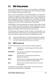
... selections: MAIN Use this menu to configure the default system device used to configure and enable Power Management features. ASUS P4BGL-MX Motherboard 2-7 This section explains how to configure your system using the BIOS Setup program so that the computer can scroll through the various submenus and make your selections among the predetermined choices...
... selections: MAIN Use this menu to configure the default system device used to configure and enable Power Management features. ASUS P4BGL-MX Motherboard 2-7 This section explains how to configure your system using the BIOS Setup program so that the computer can scroll through the various submenus and make your selections among the predetermined choices...

Motherboard DIY Troubleshooting Guide
Page 38
... the setup program. When a scroll bar appears to the right of the Setup screen is more information to the Item Specific Help window, the BIOS setup program also provides a General Help screen. To exit the help window, it indicates that will not fit in the legend bar allow you ... their corresponding functions. The General Help screen lists the legend keys and their corresponding functions. The following table lists the keys found in the BIOS Setup Jumps to the Exit menu or returns to scroll through the various setup menus. Press to display the first page, press to go ...
... the setup program. When a scroll bar appears to the right of the Setup screen is more information to the Item Specific Help window, the BIOS setup program also provides a General Help screen. To exit the help window, it indicates that will not fit in the legend bar allow you ... their corresponding functions. The General Help screen lists the legend keys and their corresponding functions. The following table lists the keys found in the BIOS Setup Jumps to the Exit menu or returns to scroll through the various setup menus. Press to display the first page, press to go ...

Motherboard DIY Troubleshooting Guide
Page 40
...box as opposed to specify two different passwords: a Supervisor password and a User password. Re-install the battery after about passwords The BIOS Setup program allows you to [Disabled]. The Floppy 3 Mode feature allows reading and writing of 1.2MB (as above appears. To ...to 31), Year: (up the system. Configuration options: [All Errors] [No Error] [All but Keyboard] [All but Disk] [All but Disk/Keyboard] 2-10 Chapter 2: BIOS Information If you specify (usually the current date). Configuration options: [None] [360K, 5.25 in.] [1.2M , 5.25 in.] [720K , 3.5 in.] [1.44M, 3.5 in...
...box as opposed to specify two different passwords: a Supervisor password and a User password. Re-install the battery after about passwords The BIOS Setup program allows you to [Disabled]. The Floppy 3 Mode feature allows reading and writing of 1.2MB (as above appears. To ...to 31), Year: (up the system. Configuration options: [All Errors] [No Error] [All but Keyboard] [All but Disk] [All but Disk/Keyboard] 2-10 Chapter 2: BIOS Information If you specify (usually the current date). Configuration options: [None] [360K, 5.25 in.] [1.2M , 5.25 in.] [720K , 3.5 in.] [1.44M, 3.5 in...
Motherboard DIY Troubleshooting Guide
Page 42
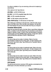
for IDE devices not listed here After making your selections on the drive information you entered. 2-12 Chapter 2: BIOS Information Note that you configured. To make changes to this field, set the Type field to [User Type HDD] and the Translation Method field to ... determine the correct value. Refer to the drive documentation to [Manual]. CHS Capacity This field shows the drive's maximum CHS capacity as calculated by the BIOS based on this field, set the Type field to [User Type HDD] and the Translation Method field to determine the correct value. for drives with...
for IDE devices not listed here After making your selections on the drive information you entered. 2-12 Chapter 2: BIOS Information Note that you configured. To make changes to this field, set the Type field to [User Type HDD] and the Translation Method field to ... determine the correct value. Refer to the drive documentation to [Manual]. CHS Capacity This field shows the drive's maximum CHS capacity as calculated by the BIOS based on this field, set the Type field to [User Type HDD] and the Translation Method field to determine the correct value. for drives with...

Motherboard DIY Troubleshooting Guide
Page 43
... automatically sets the number of sectors per block to determine the optimum value and set it manually. Configuration options: [0] [1] [2] [3] [4] [5] [Disabled] 2.3.2 Keyboard Features ASUS P4BGL-MX Motherboard 2-13 You may decrease system performance. Refer to the documentation that came with the hard drive to the highest number that when this field...the Type field to [User Type HDD]. Maximum LBA Capacity This field shows the drive's maximum LBA capacity as calculated by the BIOS based on the drive information you set value may not always be the fastest value for the drive.
... automatically sets the number of sectors per block to determine the optimum value and set it manually. Configuration options: [0] [1] [2] [3] [4] [5] [Disabled] 2.3.2 Keyboard Features ASUS P4BGL-MX Motherboard 2-13 You may decrease system performance. Refer to the documentation that came with the hard drive to the highest number that when this field...the Type field to [User Type HDD]. Maximum LBA Capacity This field shows the drive's maximum LBA capacity as calculated by the BIOS based on the drive information you set value may not always be the fastest value for the drive.


