User Guide
Page 7
... safety • Before installing devices into the system, carefully read all cables are correctly connected and the power cables are connected. • If the power supply is incorrectly replaced. Do not place the product in any damage, contact your retailer. Dispose of explosion ...hnljchen Typ. LASER PRODUCT WARNING CLASS 1 LASER PRODUCT vii Safety information Electrical safety • To prevent electrical shock hazard, disconnect the power cable from the electrical outlet before relocating the system. • When adding or removing devices to or from connectors, slots, sockets...
... safety • Before installing devices into the system, carefully read all cables are correctly connected and the power cables are connected. • If the power supply is incorrectly replaced. Do not place the product in any damage, contact your retailer. Dispose of explosion ...hnljchen Typ. LASER PRODUCT WARNING CLASS 1 LASER PRODUCT vii Safety information Electrical safety • To prevent electrical shock hazard, disconnect the power cable from the electrical outlet before relocating the system. • When adding or removing devices to or from connectors, slots, sockets...
User Guide
Page 10
... reader • 3-in-1 storage card reader • PCI riser card • 250W power supply unit 2. AH2 system package for the following items. If any of the items is damaged or missing, contact your Pundit P1 - ASUS Pundit P1 - Cable • Power cable and plug • Serial ATA power cable and signal cable • IDE cable 3. Item description 1. CDs • Support...
... reader • 3-in-1 storage card reader • PCI riser card • 250W power supply unit 2. AH2 system package for the following items. If any of the items is damaged or missing, contact your Pundit P1 - ASUS Pundit P1 - Cable • Power cable and plug • Serial ATA power cable and signal cable • IDE cable 3. Item description 1. CDs • Support...

User Guide
Page 15
...-D Out port. 8. Power supply air vents. 12. S-Video Out port. 13. LAN (RJ-45) port. 16. Parallel port. Audio 2, 4, or 6-channel configuration Port Light Blue Lime Pink Headset 2-s p e a k e r Line In Line Out Mic In 4-speaker Surround Out Front Speaker Out Mic 6-speaker Surround Out Front Speaker Out Center/Bass ASUS Pundit P1-AH2 1-5 6. USB...
...-D Out port. 8. Power supply air vents. 12. S-Video Out port. 13. LAN (RJ-45) port. 16. Parallel port. Audio 2, 4, or 6-channel configuration Port Light Blue Lime Pink Headset 2-s p e a k e r Line In Line Out Mic In 4-speaker Surround Out Front Speaker Out Mic 6-speaker Surround Out Front Speaker Out Center/Bass ASUS Pundit P1-AH2 1-5 6. USB...
User Guide
Page 16
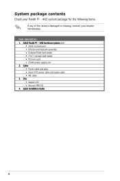
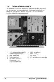
... is the internal view of the system when you remove the top cover and the power supply unit. DIMM sockets 2. Power supply unit 8. CPU socket 3. CPU fan and heatsink assembly 4. PCI card riser bracket (connected to Chapter 2 for your reference. ASUS motherboard inch hard disk drive cage 6. Front penel cover 7. The installed components are labeled...
... is the internal view of the system when you remove the top cover and the power supply unit. DIMM sockets 2. Power supply unit 8. CPU socket 3. CPU fan and heatsink assembly 4. PCI card riser bracket (connected to Chapter 2 for your reference. ASUS motherboard inch hard disk drive cage 6. Front penel cover 7. The installed components are labeled...
User Guide
Page 18
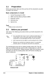
... components into the system. • Use a grounded wrist strap or touch a safely grounded object or a metal object, such as the power supply case, before installing any component, place it on them due to static electricity. • Hold components by the edges to avoid touching the... ICs on a grounded antistatic pad or in the bag that came with an onboard standby power LED. SB_PWR ON OFF Standby Powered R Power Off Onboard LED 2-2 Chapter 2: Basic installation Basic components to indicate that the system is OFF before handling components ...
... components into the system. • Use a grounded wrist strap or touch a safely grounded object or a metal object, such as the power supply case, before installing any component, place it on them due to static electricity. • Hold components by the edges to avoid touching the... ICs on a grounded antistatic pad or in the bag that came with an onboard standby power LED. SB_PWR ON OFF Standby Powered R Power Off Onboard LED 2-2 Chapter 2: Basic installation Basic components to indicate that the system is OFF before handling components ...
User Guide
Page 29
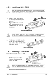
Locked Retaining Clip 2.8.3 Removing a DDR2 DIMM Follow these steps to unplug the power supply before adding or removing DIMMs or other system components. The DIMM might get damaged when it fits in place and the DIMM is keyed ... a notch so that the notch on the DIMM matches the break on the socket. 1 Unlocked retaining clip 2 DDR2 DIMM notch 1 A DDR2 DIMM is properly seated. ASUS Pundit P1-AH2 2-11 2.8.2 Installing a DDR2 DIMM Make sure to remove a DIMM. 2 1. Remove the DIMM from the socket. Align a DIMM on the socket such that it flips...
Locked Retaining Clip 2.8.3 Removing a DDR2 DIMM Follow these steps to unplug the power supply before adding or removing DIMMs or other system components. The DIMM might get damaged when it fits in place and the DIMM is keyed ... a notch so that the notch on the DIMM matches the break on the socket. 1 Unlocked retaining clip 2 DDR2 DIMM notch 1 A DDR2 DIMM is properly seated. ASUS Pundit P1-AH2 2-11 2.8.2 Installing a DDR2 DIMM Make sure to remove a DIMM. 2 1. Remove the DIMM from the socket. Align a DIMM on the socket such that it flips...
User Guide
Page 53
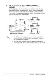
... (3-pin USBPW12, USBPW34, USBPW56) Set these jumpers to +5V to CPU, DRAM in slow refresh, power supply in reduced power mode). USBPW56 12 23 +5V(Default) +5VSB USBPW34 12 23 R +5V(Default) +5VSB USBPW12 21 32 USB device Wake up +5V(Default) +5VSB • The ... (CPU stopped, DRAM refreshed, system running in sleep mode. 4-4 Chapter 4: Motherboard info Set to +5VSB to wake up from S3 and S4 sleep modes (no power to wake up feature requires a power supply that can provide 500mA on the +5VSB lead for each USB port;
... (3-pin USBPW12, USBPW34, USBPW56) Set these jumpers to +5V to CPU, DRAM in slow refresh, power supply in reduced power mode). USBPW56 12 23 +5V(Default) +5VSB USBPW34 12 23 R +5V(Default) +5VSB USBPW12 21 32 USB device Wake up +5V(Default) +5VSB • The ... (CPU stopped, DRAM refreshed, system running in sleep mode. 4-4 Chapter 4: Motherboard info Set to +5VSB to wake up from S3 and S4 sleep modes (no power to wake up feature requires a power supply that can provide 500mA on the +5VSB lead for each USB port;

User Guide
Page 57
... PSON# Ground Ground Ground -5 Volts +5 Volts +5 Volts +5 Volts Ground ATX Power Connector ATX12V GND +12V DC • Do not forget to receive stereo audio input from the power supply are for ATX power supply plugs. R CD (black) Internal Audio Connector Right Audio Channel Ground Ground Left Audio...may become unstable or may not boot up if the power is recommended when configuring a system with a higher power output is inadequate. • Make sure that your power supply unit (PSU) can provide at least the minimum power required by your system. 7. otherwise, the system will...
... PSON# Ground Ground Ground -5 Volts +5 Volts +5 Volts +5 Volts Ground ATX Power Connector ATX12V GND +12V DC • Do not forget to receive stereo audio input from the power supply are for ATX power supply plugs. R CD (black) Internal Audio Connector Right Audio Channel Ground Ground Left Audio...may become unstable or may not boot up if the power is recommended when configuring a system with a higher power output is inadequate. • Make sure that your power supply unit (PSU) can provide at least the minimum power required by your system. 7. otherwise, the system will...


