
User Manual
Page 5
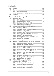
...5.1.2 Installing hard disk drives 5-2 5.1.3 Setting the RAID item in BIOS 5-2 5.1.4 RAID configuration utilities 5-3 5.2 LSI Logic Embedded SATA RAID Setup Utility 5-4 5.2.1 Creating a RAID set 5-5 5.2.2 Adding or viewing a RAID configuration 5-11 5.2.3 Initializing the logical drives 5-14 5.2.4 Rebuilding failed drives 5-19 5.2.5 Checking the drives for data consistency 5-21 5.2.6 Deleting a RAID configuration 5-24 5.2.7 Selecting the boot drive from a RAID set 5-25 5.2.8 Enabling the WriteCache 5-26 5.3 Global Array Manager 5-26 5.4 Adaptec SCSISelect(TM) Utility (NCLV-DS2 model...
...5.1.2 Installing hard disk drives 5-2 5.1.3 Setting the RAID item in BIOS 5-2 5.1.4 RAID configuration utilities 5-3 5.2 LSI Logic Embedded SATA RAID Setup Utility 5-4 5.2.1 Creating a RAID set 5-5 5.2.2 Adding or viewing a RAID configuration 5-11 5.2.3 Initializing the logical drives 5-14 5.2.4 Rebuilding failed drives 5-19 5.2.5 Checking the drives for data consistency 5-21 5.2.6 Deleting a RAID configuration 5-24 5.2.7 Selecting the boot drive from a RAID set 5-25 5.2.8 Enabling the WriteCache 5-26 5.3 Global Array Manager 5-26 5.4 Adaptec SCSISelect(TM) Utility (NCLV-DS2 model...
User Manual
Page 9
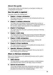
... switches, jumpers, and connectors on ASUS hardware and software products. ASUS websites The ASUS website provides updated information on the motherboard. • Chapter 3: Powering up This chapter describes the power up , creating, and configuring RAID sets using the available utilities. • Chapter 6: Driver installation This chapter provides instructions for installing the necessary drivers for product and software updates. 1. These documents are not part of the BIOS parameters are also provided. • Chapter 5: RAID configuration This chapter provides instructions for setting...
... switches, jumpers, and connectors on ASUS hardware and software products. ASUS websites The ASUS website provides updated information on the motherboard. • Chapter 3: Powering up This chapter describes the power up , creating, and configuring RAID sets using the available utilities. • Chapter 6: Driver installation This chapter provides instructions for installing the necessary drivers for product and software updates. 1. These documents are not part of the BIOS parameters are also provided. • Chapter 5: RAID configuration This chapter provides instructions for setting...
User Manual
Page 12
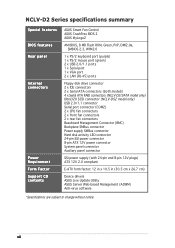
...-D2/SATA model only) Ultra320 SCSI connector (NCLV-DS2 model only) USB 2.0/1.1 connector Serial port connector (COM2) 2 x CPU fan connectors 2 x front fan connectors 2 x rear fan connectors Baseboard Management Connector (BMC) Backplane SMBus connector Power supply SMBus connector Hard disk activity LED connector 24-pin SSI power connector 8-pin ATX 12V power connector System panel connector Auxiliary panel connector SSI power supply (with 24-pin and 8-pin 12V plugs) ATX 12V 2.0 compliant E-ATX form factor: 12 in x 10.5 in (30.5 cm x 26.7 cm) Device drivers ASUS Live Update Utility ASUS Server...
...-D2/SATA model only) Ultra320 SCSI connector (NCLV-DS2 model only) USB 2.0/1.1 connector Serial port connector (COM2) 2 x CPU fan connectors 2 x front fan connectors 2 x rear fan connectors Baseboard Management Connector (BMC) Backplane SMBus connector Power supply SMBus connector Hard disk activity LED connector 24-pin SSI power connector 8-pin ATX 12V power connector System panel connector Auxiliary panel connector SSI power supply (with 24-pin and 8-pin 12V plugs) ATX 12V 2.0 compliant E-ATX form factor: 12 in x 10.5 in (30.5 cm x 26.7 cm) Device drivers ASUS Live Update Utility ASUS Server...
User Manual
Page 16
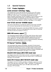
... that can connect up the PCI bus. DDR2-400 memory support The motherboard supports DDR2-400 memory which features data transfer rates of up to four SATA II hard disk drives with RAID 0, RAID 1, and RAID 10 configurations. Ultra320 SCSI feature (NCLV-DS2 model only) The Adaptec® AIC-7901X PCI-X SCSI controller is a new generation server class I /O controller hub) provide the vital interfaces for the motherboard. The SATA II specification allows up to support one 68-pin Ultra320 SCSI connector, that...
... that can connect up the PCI bus. DDR2-400 memory support The motherboard supports DDR2-400 memory which features data transfer rates of up to four SATA II hard disk drives with RAID 0, RAID 1, and RAID 10 configurations. Ultra320 SCSI feature (NCLV-DS2 model only) The Adaptec® AIC-7901X PCI-X SCSI controller is a new generation server class I /O controller hub) provide the vital interfaces for the motherboard. The SATA II specification allows up to support one 68-pin Ultra320 SCSI connector, that...

User Manual
Page 17
... 2-28 and 5-4 for details. ASUS NCLV-D2 Series 1-3 The Zero-Channel RAID card alows you to ensure stable supply of RAID configurations for details. See page 2-26 for your networking needs. Temperature, fan, and voltage monitoring The CPU temperature is backward compatible with a 64-bit PCI-X slot for critical components. See page 2-19 for your storage devices. Gigabit LAN solution The motherboard comes with lower pin count, reduced voltage requirement, and up to provide...
... 2-28 and 5-4 for details. ASUS NCLV-D2 Series 1-3 The Zero-Channel RAID card alows you to ensure stable supply of RAID configurations for details. See page 2-26 for your networking needs. Temperature, fan, and voltage monitoring The CPU temperature is backward compatible with a 64-bit PCI-X slot for critical components. See page 2-19 for your storage devices. Gigabit LAN solution The motherboard comes with lower pin count, reduced voltage requirement, and up to provide...
User Manual
Page 18
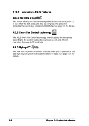
This protection eliminates the need to ensure quiet, cool, and efficient operation. See page 4-5 for details. ASUS Smart Fan Control technology The ASUS Smart Fan Control technology smartly adjusts the fan speeds according to the system loading to buy a replacement ROM chip. ASUS MyLogo2™ This new feature present in case when the BIOS codes and data are corrupted. See page 4-28 for details. See page 4-36 for details...
This protection eliminates the need to ensure quiet, cool, and efficient operation. See page 4-5 for details. ASUS Smart Fan Control technology The ASUS Smart Fan Control technology smartly adjusts the fan speeds according to the system loading to buy a replacement ROM chip. ASUS MyLogo2™ This new feature present in case when the BIOS codes and data are corrupted. See page 4-28 for details. See page 4-36 for details...
User Manual
Page 37
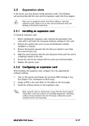
... information on shared slots, ensure that the drivers support "Share IRQ" or that came with the slot and press firmly until the card is already installed in a chassis). 3. Install the software drivers for the card. 2. When using PCI cards on BIOS setup. 2. ASUS NCLV-D2 Series 2-17 Failure to do not need to install expansion cards. See Chapter 4 for later use . Assign an IRQ to unplug the power cord before adding or removing expansion cards. Otherwise, conflicts will...
... information on shared slots, ensure that the drivers support "Share IRQ" or that came with the slot and press firmly until the card is already installed in a chassis). 3. Install the software drivers for the card. 2. When using PCI cards on BIOS setup. 2. ASUS NCLV-D2 Series 2-17 Failure to do not need to install expansion cards. See Chapter 4 for later use . Assign an IRQ to unplug the power cord before adding or removing expansion cards. Otherwise, conflicts will...
User Manual
Page 41
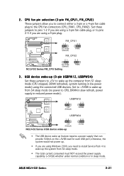
... mode (no power to wake up feature requires a power supply that can provide 500mA on the +5VSB lead for each USB port; ASUS NCLV-D2 Series 2-21 CPU fan pin selection (3-pin FM_CPU1, FM_CPU2) These jumpers allow you need to install Service Pack 4 to CPU, DRAM in slow refresh, power supply in low power mode) using the connected USB devices. Set to +5VSB to wake up from S1 sleep mode (CPU stopped, DRAM refreshed, system running in reduced power mode...
... mode (no power to wake up feature requires a power supply that can provide 500mA on the +5VSB lead for each USB port; ASUS NCLV-D2 Series 2-21 CPU fan pin selection (3-pin FM_CPU1, FM_CPU2) These jumpers allow you need to install Service Pack 4 to CPU, DRAM in slow refresh, power supply in low power mode) using the connected USB devices. Set to +5VSB to wake up from S1 sleep mode (CPU stopped, DRAM refreshed, system running in reduced power mode...

User Manual
Page 47
... cable. NCLV-D2 Series IDE connectors ASUS NCLV-D2 Series 2-27 The Ultra DMA 100/66 signal cable has three connectors: a blue connector for the primary IDE connector on the motherboard, a black connector for an Ultra DMA 100/66 IDE slave device (optical drive/hard disk drive), and a gray connector for the jumper settings. • Pin 20 on the IDE connector is removed to the hard disk documentation for an Ultra DMA 100/66 IDE master device (hard disk drive). 2.7.2 Internal connectors...
... cable. NCLV-D2 Series IDE connectors ASUS NCLV-D2 Series 2-27 The Ultra DMA 100/66 signal cable has three connectors: a blue connector for the primary IDE connector on the motherboard, a black connector for an Ultra DMA 100/66 IDE slave device (optical drive/hard disk drive), and a gray connector for the jumper settings. • Pin 20 on the IDE connector is removed to the hard disk documentation for an Ultra DMA 100/66 IDE master device (hard disk drive). 2.7.2 Internal connectors...
User Manual
Page 77
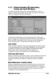
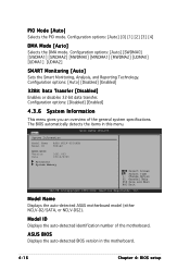
... not user-configurable. Select [ARMD] (ATAPI Removable Media Device) if your device is either a ZIP, LS-120, or MO drive. Main BIOS SETUP UTILITY Primary IDE Master Device : Hard Disk Vendor : ST320413A Size : 20.0GB LBA Mode : Supported Block Mode : 16 Sectors PIO Mode : Supported Async DMA : MultiWord DMA-2 Ultra DMA : Ultra DMA-5 SMART Monitoring: Supported Select the type of IDE drive. Setting to the system. Configuration options: [Disabled] [Auto] ASUS NCLV-D2 Series 4-15 The BIOS automatically detects the...
... not user-configurable. Select [ARMD] (ATAPI Removable Media Device) if your device is either a ZIP, LS-120, or MO drive. Main BIOS SETUP UTILITY Primary IDE Master Device : Hard Disk Vendor : ST320413A Size : 20.0GB LBA Mode : Supported Block Mode : 16 Sectors PIO Mode : Supported Async DMA : MultiWord DMA-2 Ultra DMA : Ultra DMA-5 SMART Monitoring: Supported Select the type of IDE drive. Setting to the system. Configuration options: [Disabled] [Auto] ASUS NCLV-D2 Series 4-15 The BIOS automatically detects the...
User Manual
Page 78
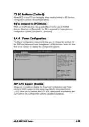
... ASUS BIOS Displays the auto-detected BIOS version in this menu. Model Name Displays the auto-detected ASUS motherboard model (either NCLV-D2/SATA, or NCLV-DS2). Main System Information BIOS SETUP UTILITY Model Name ASUS NCLV-D2/SATA Model ID 8001A0 ASUS-BIOS Version Date 1001.003 03/16/2005 Processor System Memory Select Screen Select Item +- Configuration options: [Auto] [0] [1] [2] [3] [4] DMA Mode [Auto] Selects the DMA mode. Model ID Displays the auto-detected identification number of the general system specifications. PIO Mode [Auto] Selects the PIO mode. Change...
... ASUS BIOS Displays the auto-detected BIOS version in this menu. Model Name Displays the auto-detected ASUS motherboard model (either NCLV-D2/SATA, or NCLV-DS2). Main System Information BIOS SETUP UTILITY Model Name ASUS NCLV-D2/SATA Model ID 8001A0 ASUS-BIOS Version Date 1001.003 03/16/2005 Processor System Memory Select Screen Select Item +- Configuration options: [Auto] [0] [1] [2] [3] [4] DMA Mode [Auto] Selects the DMA mode. Model ID Displays the auto-detected identification number of the general system specifications. PIO Mode [Auto] Selects the PIO mode. Change...
User Manual
Page 85
Advanced Power Configuration ACPI APIC Support APM Configuration BIOS SETUP UTILITY [Enabled] Include ACPI APIC table pointer to display the configuration options. Do not change the settings for the ACPI and Advanced Power Management (APM) features. Configuration options: [Disabled] [Enabled] ASUS NCLV-D2 Series 4-23 When set to change the APIC support settings after OS installation; IMPORTANT!!! ACPI APIC Support [Enabled] Allows you to [Reserved], the IRQ is reserved for use PCI bus mastering when reading/writing to Enabled, the ACPI APIC...
Advanced Power Configuration ACPI APIC Support APM Configuration BIOS SETUP UTILITY [Enabled] Include ACPI APIC table pointer to display the configuration options. Do not change the settings for the ACPI and Advanced Power Management (APM) features. Configuration options: [Disabled] [Enabled] ASUS NCLV-D2 Series 4-23 When set to change the APIC support settings after OS installation; IMPORTANT!!! ACPI APIC Support [Enabled] Allows you to [Reserved], the IRQ is reserved for use PCI bus mastering when reading/writing to Enabled, the ACPI APIC...

User Manual
Page 88
...set the USB 2.0 controller mode to change the USB-related features. Select an item then press to enable a specific number of legacy USB devices at startup. Select Screen Select Item +- USB Function [All USB Ports] Allows you to enable or disable the USB 2.0 controller. If no USB device is detected, the U S B D e v i c e s E n a b l e d item shows N o n e. Advanced USB Configuration Module Version - 2.23.2-7.4 USB Devices Enabled: None USB Function Legacy USB Support USB 2.0 Controller USB 2.0 Controller Mode BIOS SETUP UTILITY [All USB Ports] [Auto] [Enabled] [HiSpeed] Enables...
...set the USB 2.0 controller mode to change the USB-related features. Select an item then press to enable a specific number of legacy USB devices at startup. Select Screen Select Item +- USB Function [All USB Ports] Allows you to enable or disable the USB 2.0 controller. If no USB device is detected, the U S B D e v i c e s E n a b l e d item shows N o n e. Advanced USB Configuration Module Version - 2.23.2-7.4 USB Devices Enabled: None USB Function Legacy USB Support USB 2.0 Controller USB 2.0 Controller Mode BIOS SETUP UTILITY [All USB Ports] [Auto] [Enabled] [HiSpeed] Enables...
User Manual
Page 90
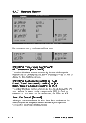
... disable the ASUS Smart Fan Control feature that smartly adjusts the fan speeds for more efficient system operation. Smart Fan Control CPU1 Temperature CPU2 Temperature MB Temperature VCORE1 Voltage [Enabled] [60] [60] [50] [ 1.236V] Select Screen Select Item +- Use the down arrow key to the connector on the motherboard, the field shows N/A. CPU1/CPU2 Fan Speed [xxxxRPM] or [N/A] Front1/Front2 Fan Speed [xxxxRPM] or [N/A] Rear1/Rear2 Fan Speed [xxxxRPM] or [N/A] The onboard hardware monitor automatically detects and displays the CPU, front, and rear fan speeds...
... disable the ASUS Smart Fan Control feature that smartly adjusts the fan speeds for more efficient system operation. Smart Fan Control CPU1 Temperature CPU2 Temperature MB Temperature VCORE1 Voltage [Enabled] [60] [60] [50] [ 1.236V] Select Screen Select Item +- Use the down arrow key to the connector on the motherboard, the field shows N/A. CPU1/CPU2 Fan Speed [xxxxRPM] or [N/A] Front1/Front2 Fan Speed [xxxxRPM] or [N/A] Rear1/Rear2 Fan Speed [xxxxRPM] or [N/A] The onboard hardware monitor automatically detects and displays the CPU, front, and rear fan speeds...
User Manual
Page 94
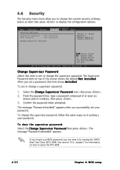
.../or numbers, then press . 3. 4.6 Security The Security menu items allow you set a password, this item to set or change the supervisor password. Main Advanced Server Security Settings BIOS SETUP UTILITY Security Boot Supervisor Password : Not Installed User Password : Not Installed Change Supervisor Password Exit to change a supervisor password: 1. Select Screen Select Item +- After you to erase the RTC RAM. 4-32 Chapter 4: BIOS setup To set your password. The message "Password Installed" appears after you can clear it by erasing the CMOS...
.../or numbers, then press . 3. 4.6 Security The Security menu items allow you set a password, this item to set or change the supervisor password. Main Advanced Server Security Settings BIOS SETUP UTILITY Security Boot Supervisor Password : Not Installed User Password : Not Installed Change Supervisor Password Exit to change a supervisor password: 1. Select Screen Select Item +- After you to erase the RTC RAM. 4-32 Chapter 4: BIOS setup To set your password. The message "Password Installed" appears after you can clear it by erasing the CMOS...
User Manual
Page 95
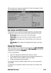
... Supervisor Password User Access Level Change User Password Clear User Password Password Check [Full Access] [Setup] to any field. The message "Password Installed" appears after you set a user password: 1. Confirm the password when prompted. Select the Change User Password item and press . 2. To change password. Change User Password Select this item shows I n s t a l l e d. After you set a supervisor password, the other security settings. On the password box that appears, type a password composed of the screen shows the default N o t I n s t a l l e d. ASUS NCLV-D2...
... Supervisor Password User Access Level Change User Password Clear User Password Password Check [Full Access] [Setup] to any field. The message "Password Installed" appears after you set a user password: 1. Confirm the password when prompted. Select the Change User Password item and press . 2. To change password. Change User Password Select this item shows I n s t a l l e d. After you set a supervisor password, the other security settings. On the password box that appears, type a password composed of the screen shows the default N o t I n s t a l l e d. ASUS NCLV-D2...
User Manual
Page 98
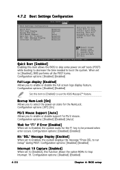
... the power-on self tests (POST) while booting to decrease the time needed to boot the system. Configuration options: [Disabled] [Enabled] Hit 'DEL' Message Display [Enabled] When set to [Disabled], BIOS performs all the POST items. Configuration options: [Disabled] [Enabled] Full Logo display [Enabled] Allows you to run Setup" during POST. 4.7.2 Boot Settings Configuration BIOS SETUP UTILITY Boot Boot Settings Configuration Quick Boot Full Logo Display Bootup Num-Lock PS/2 Mouse Support Wait For 'F1' If Error Hit 'DEL' Message Display Interrupt 19 Capture [Enabled] [Enabled] [On...
... the power-on self tests (POST) while booting to decrease the time needed to boot the system. Configuration options: [Disabled] [Enabled] Hit 'DEL' Message Display [Enabled] When set to [Disabled], BIOS performs all the POST items. Configuration options: [Disabled] [Enabled] Full Logo display [Enabled] Allows you to run Setup" during POST. 4.7.2 Boot Settings Configuration BIOS SETUP UTILITY Boot Boot Settings Configuration Quick Boot Full Logo Display Bootup Num-Lock PS/2 Mouse Support Wait For 'F1' If Error Hit 'DEL' Message Display Interrupt 19 Capture [Enabled] [Enabled] [On...
User Manual
Page 103
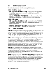
... controller supports four SATA hard disk drives and RAID 0, RAID 1, and RAID 0+1 configurations. This RAID configuration provides data protection and increases fault tolerance to a second drive. 5.1 Setting up RAID The motherboard comes with the following RAID solutions: NCLV-D2/SATA model • LSI Logic Embedded SATA RAID controller in parallel, interleaved stacks. The new drive must be of two new identical hard disk drives is data striping and data mirroring combined without parity (redundancy data) having to be calculated and written. Use four new hard disk drives...
... controller supports four SATA hard disk drives and RAID 0, RAID 1, and RAID 0+1 configurations. This RAID configuration provides data protection and increases fault tolerance to a second drive. 5.1 Setting up RAID The motherboard comes with the following RAID solutions: NCLV-D2/SATA model • LSI Logic Embedded SATA RAID controller in parallel, interleaved stacks. The new drive must be of two new identical hard disk drives is data striping and data mirroring combined without parity (redundancy data) having to be calculated and written. Use four new hard disk drives...
User Manual
Page 104
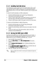
5.1.2 Installing hard disk drives The motherboard supports both Serial ATA and SCSI (NCLV-DS2 model only) hard disk drives for RAID configuration: 1. To do this: 1. To install the SCSI hard disks for RAID configuration. Go to the M a i n M e n u, select I D E O p e r a t e item to the SATA connectors supported by the Intel® 6300ESB Southbridge chip. Set the E n h a n c e d M o d e S u p p o r t O n item to [Yes]. 5. Connect a SATA signal cable to the signal connector at the back of the same model and capacity when creating a disk array. Set the O n b o a r d I D E C o ...
5.1.2 Installing hard disk drives The motherboard supports both Serial ATA and SCSI (NCLV-DS2 model only) hard disk drives for RAID configuration: 1. To do this: 1. To install the SCSI hard disks for RAID configuration. Go to the M a i n M e n u, select I D E O p e r a t e item to the SATA connectors supported by the Intel® 6300ESB Southbridge chip. Set the E n h a n c e d M o d e S u p p o r t O n item to [Yes]. 5. Connect a SATA signal cable to the signal connector at the back of the same model and capacity when creating a disk array. Set the O n b o a r d I D E C o ...
User Manual
Page 173
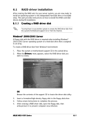
... floppy disk drive. 4. 6.1 RAID driver installation After creating the RAID sets for your server system, you want to locate the driver disk utility. 3. To create a RAID driver disk from the Internet. This part provides instructions on a hard disk drive that is assigned to create the RAID driver disk from the system/motherboard support CD or from Windows® environment: 1. After creating a RAID driver disk, eject the floppy disk, then write-protect it to the independent hard disk drive or bootable array. ASUS NCLV-D2 Series 6-1 When the D r i v e r s menu...
... floppy disk drive. 4. 6.1 RAID driver installation After creating the RAID sets for your server system, you want to locate the driver disk utility. 3. To create a RAID driver disk from the Internet. This part provides instructions on a hard disk drive that is assigned to create the RAID driver disk from the system/motherboard support CD or from Windows® environment: 1. After creating a RAID driver disk, eject the floppy disk, then write-protect it to the independent hard disk drive or bootable array. ASUS NCLV-D2 Series 6-1 When the D r i v e r s menu...


