User Manual
Page 6
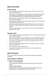
Contact a qualified service technician or your dealer immediately. • To avoid short circuits, keep paper clips, screws, and staples away from connectors, slots, sockets, and circuitry. • Avoid dust, humidity, and temperature extremes. About this guide is organized This guide contains the following parts: • Chapter 1: Product introduction This ...
Contact a qualified service technician or your dealer immediately. • To avoid short circuits, keep paper clips, screws, and staples away from connectors, slots, sockets, and circuitry. • Avoid dust, humidity, and temperature extremes. About this guide is organized This guide contains the following parts: • Chapter 1: Product introduction This ...
User Manual
Page 8
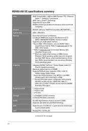
...less than 3GB is supported per channel. Hence, a total installed memory of 256MB Supports RGB with max. Refer to www.asus.com for the AM2+ CPU models. ** Refer to www.asus.com for AMD Phenom™FX / Phenom / Athlon™ / Sempron™ processors AMD Cool 'n' Quiet™ ... 4 ports at back panel) Realtek PHY 10/100 LAN (continued on the next page) viii M2N68-AM SE specifications summary CPU Chipset System bus Memory Graphics Expansion slots Storage Audio USB LAN AMD® Socket AM2+ / AM2 for the latest Memory QVL (Qualified Vendors List). *** When you are using a...
...less than 3GB is supported per channel. Hence, a total installed memory of 256MB Supports RGB with max. Refer to www.asus.com for the AM2+ CPU models. ** Refer to www.asus.com for AMD Phenom™FX / Phenom / Athlon™ / Sempron™ processors AMD Cool 'n' Quiet™ ... 4 ports at back panel) Realtek PHY 10/100 LAN (continued on the next page) viii M2N68-AM SE specifications summary CPU Chipset System bus Memory Graphics Expansion slots Storage Audio USB LAN AMD® Socket AM2+ / AM2 for the latest Memory QVL (Qualified Vendors List). *** When you are using a...
User Manual
Page 10
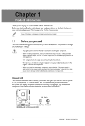
Failure to do so may cause severe damage to page ix for buying an ASUS® M2N68-AM SE motherboard! M2N68-AM SE SB_PWR ON OFF Standby Power Powered Off M2N68-AM SE Onboard LED 1-1 Chapter 1: Product introduction If any of the following precautions before you install motherboard components or change...due to static electricity • Hold components by the edges to indicate that the system is detached from the wall socket before removing or plugging in any motherboard component. The illustration below shows the location of accessories. Refer to the motherboard, peripherals,...
Failure to do so may cause severe damage to page ix for buying an ASUS® M2N68-AM SE motherboard! M2N68-AM SE SB_PWR ON OFF Standby Power Powered Off M2N68-AM SE Onboard LED 1-1 Chapter 1: Product introduction If any of the following precautions before you install motherboard components or change...due to static electricity • Hold components by the edges to indicate that the system is detached from the wall socket before removing or plugging in any motherboard component. The illustration below shows the location of accessories. Refer to the motherboard, peripherals,...
User Manual
Page 11
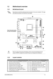
...to the rear part of the chassis. 16 15 USB34 24.4cm(9.6in) LAN1_USB12 AUDIO RTL 8201CP USBPW1-4 Super I/O CPU_FAN M2N68-AM SE PCIEX16 Lithium Cell CMOS Power PCIEX1_1 NVIDIA® MCP68PVNT PRI_IDE SATA1 SATA2 ALC 662 CD AAFP 13 12 PCI1 F_PANEL SB_PWR CLRTC...PCIe x1/PCI slot Page 1-13 1-1 1-14 1-11 1-14 1-3 1-3 1-7 ASUS M2N68-AM SE 1-2 ATX power connectors (24-pin EATXPWR, 4-pin ATX12V) 2. Serial ATA connectors (7-pin SATA1, SATA2) 5. Optical drive audio connector (4-pin CD) 1-8 13. AM2 CPU Socket 1-12 15. Internal speaker connector (4-pin SPEAKER) 1-11 10. The edge ...
...to the rear part of the chassis. 16 15 USB34 24.4cm(9.6in) LAN1_USB12 AUDIO RTL 8201CP USBPW1-4 Super I/O CPU_FAN M2N68-AM SE PCIEX16 Lithium Cell CMOS Power PCIEX1_1 NVIDIA® MCP68PVNT PRI_IDE SATA1 SATA2 ALC 662 CD AAFP 13 12 PCI1 F_PANEL SB_PWR CLRTC...PCIe x1/PCI slot Page 1-13 1-1 1-14 1-11 1-14 1-3 1-3 1-7 ASUS M2N68-AM SE 1-2 ATX power connectors (24-pin EATXPWR, 4-pin ATX12V) 2. Serial ATA connectors (7-pin SATA1, SATA2) 5. Optical drive audio connector (4-pin CD) 1-8 13. AM2 CPU Socket 1-12 15. Internal speaker connector (4-pin SPEAKER) 1-11 10. The edge ...

User Manual
Page 12
... Unit (CPU) This motherboard comes with two Double Data Rate 2 (DDR2) Dual Inline Memory Modules (DIMM) sockets. The figure illustrates the location of the DDR2 DIMM sockets: DIMM_A1 DIMM_B1 M2N68-AM SE M2N68-AM SE 240-pin DDR2 DIMM sockets Channel Channel A Channel B Sockets DIMM_A1 DIMM_B1 1-3 Chapter 1: Product introduction Use a CPU that is designed for the AM2+ / AM2...
... Unit (CPU) This motherboard comes with two Double Data Rate 2 (DDR2) Dual Inline Memory Modules (DIMM) sockets. The figure illustrates the location of the DDR2 DIMM sockets: DIMM_A1 DIMM_B1 M2N68-AM SE M2N68-AM SE 240-pin DDR2 DIMM sockets Channel Channel A Channel B Sockets DIMM_A1 DIMM_B1 1-3 Chapter 1: Product introduction Use a CPU that is designed for the AM2+ / AM2...
User Manual
Page 13
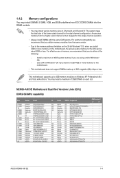
..., the actual usable memory for the single-channel operation. • Always install DIMMs with the same CAS latency. M2N68-AM SE Motherboard Qualified Vendors Lists (QVL) DDR2-533MHz capability Size 256MB 512MB 1G 256MB 512MB 256MB 1G 512MB 512MB 1G 512MB...• • • • • • • • • • ASUS M2N68-AM SE 1-4 1.4.2 Memory configurations You may install 256MB, 512MB, 1GB, and 2GB unbuffered non-ECC DDR2 DIMMs into the DIMM sockets. • You may install a maximum of 2GB DIMMs on each slot. Install a maximum of 3GB system...
..., the actual usable memory for the single-channel operation. • Always install DIMMs with the same CAS latency. M2N68-AM SE Motherboard Qualified Vendors Lists (QVL) DDR2-533MHz capability Size 256MB 512MB 1G 256MB 512MB 256MB 1G 512MB 512MB 1G 512MB...• • • • • • • • • • ASUS M2N68-AM SE 1-4 1.4.2 Memory configurations You may install 256MB, 512MB, 1GB, and 2GB unbuffered non-ECC DDR2 DIMMs into the DIMM sockets. • You may install a maximum of 2GB DIMMs on each slot. Install a maximum of 3GB system...


