
User Manual
Page 31
ok A:\> 當 BIOS DOS 31 Reading flash ..... done Write to file...... All rights reserved. exe 2 DOS afudos /o[filename filename A:\>afudos /oOLDBIOS1.rom 3. 按下 afudos /oOLDBIOS1.rom AMI Firmware Update Utility - Version 1.19(ASUS V2.07(03.11.24BB)) Copyright (C) 2002 American Megatrends, Inc. BIOS 2.1 使用 AFUDOS BIOS AFUDOS DOS BIOS BIOS 程式。AFUDOS BIOS BIOS BIOS 程式 BIOS 程式。 1.2MB BIOS 1 AFUDOS 程式(afudos.
ok A:\> 當 BIOS DOS 31 Reading flash ..... done Write to file...... All rights reserved. exe 2 DOS afudos /o[filename filename A:\>afudos /oOLDBIOS1.rom 3. 按下 afudos /oOLDBIOS1.rom AMI Firmware Update Utility - Version 1.19(ASUS V2.07(03.11.24BB)) Copyright (C) 2002 American Megatrends, Inc. BIOS 2.1 使用 AFUDOS BIOS AFUDOS DOS BIOS BIOS 程式。AFUDOS BIOS BIOS BIOS 程式 BIOS 程式。 1.2MB BIOS 1 AFUDOS 程式(afudos.

User Manual
Page 32
...-VM DO.ROM AMI Firmware Update Utility - Do not turn off power during flash BIOS Reading file ....... 更新 BIOS 程式 AFUDOS BIOS 程式。 1 tw.asus.com BIOS 片中。 BIOS BIOS 2. 將 AFUDOS.EXE BIOS 3 DOS afudos /i[filename filename BIOS 程式。 A:\>afudos /iP5B-VM DO.ROM 4. done Advance Check ...... Erasing flash ...... All...
...-VM DO.ROM AMI Firmware Update Utility - Do not turn off power during flash BIOS Reading file ....... 更新 BIOS 程式 AFUDOS BIOS 程式。 1 tw.asus.com BIOS 片中。 BIOS BIOS 2. 將 AFUDOS.EXE BIOS 3 DOS afudos /i[filename filename BIOS 程式。 A:\>afudos /iP5B-VM DO.ROM 4. done Advance Check ...... Erasing flash ...... All...

User Manual
Page 33
... 程式(AWDFLASH.EXE BIOS AwardBIOS Flash BIOS 程式。 1 http://tw.asus.com BIOS M2N-VM HDMI.bin FAT 32/16 格式的 USB BIOS 2 CD/DVD AwardBIOS Flash BIOS 3 DOS 4. 當 A BIOS 檔案與 AwardBIOS Flash 5 A awdflash 並按下 鍵。 AwardBIOS Flash Utility for ASUS V1.14 (C) Phoenix Technologies Ltd...
... 程式(AWDFLASH.EXE BIOS AwardBIOS Flash BIOS 程式。 1 http://tw.asus.com BIOS M2N-VM HDMI.bin FAT 32/16 格式的 USB BIOS 2 CD/DVD AwardBIOS Flash BIOS 3 DOS 4. 當 A BIOS 檔案與 AwardBIOS Flash 5 A awdflash 並按下 鍵。 AwardBIOS Flash Utility for ASUS V1.14 (C) Phoenix Technologies Ltd...

User Manual
Page 34
OFE00 OK Write OK No Update Write Fail Warning: Don't Turn Off Power Or Reset System! 在更新 BIOS 9 Flash Complete BIOS F1 AwardBIOS Flash Utility for ASUS V1.14 (C) Phoenix Technologies Ltd. All Rights Reserved For C51PV-MCP51-M2A-VM HDMI-00 DATE:04/13/2006 Flash Type - PMC Pm49FL004T LPC/FWH...
OFE00 OK Write OK No Update Write Fail Warning: Don't Turn Off Power Or Reset System! 在更新 BIOS 9 Flash Complete BIOS F1 AwardBIOS Flash Utility for ASUS V1.14 (C) Phoenix Technologies Ltd. All Rights Reserved For C51PV-MCP51-M2A-VM HDMI-00 DATE:04/13/2006 Flash Type - PMC Pm49FL004T LPC/FWH...
User Manual
Page 3
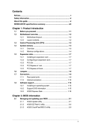
Contents Notices...v Safety information vi About this guide vi M2N68-AM SE specifications summary viii Chapter 1: Product introduction 1.1 Before you proceed 1-1 1.2 Motherboard overview 1-2 1.2.1 Motherboard layout 1-2 1.2.2 Layout contents 1-2 ...1.7.2 Internal connectors 1-10 1.8 Software support 1-15 1.8.1 Installing an operating system 1-15 1.8.2 Support DVD information 1-15 1.8.3 ASUS Express Gate 1-16 Chapter 2: BIOS information 2.1 Managing and updating your BIOS 2-1 2.1.1 ASUS Update utility 2-1 2.1.2 ASUS EZ Flash 2 utility 2-2 2.1.3 ASUS CrashFree BIOS 3 utility 2-3 iii
Contents Notices...v Safety information vi About this guide vi M2N68-AM SE specifications summary viii Chapter 1: Product introduction 1.1 Before you proceed 1-1 1.2 Motherboard overview 1-2 1.2.1 Motherboard layout 1-2 1.2.2 Layout contents 1-2 ...1.7.2 Internal connectors 1-10 1.8 Software support 1-15 1.8.1 Installing an operating system 1-15 1.8.2 Support DVD information 1-15 1.8.3 ASUS Express Gate 1-16 Chapter 2: BIOS information 2.1 Managing and updating your BIOS 2-1 2.1.1 ASUS Update utility 2-1 2.1.2 ASUS EZ Flash 2 utility 2-2 2.1.3 ASUS CrashFree BIOS 3 utility 2-3 iii
User Manual
Page 6
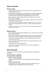
...About this guide is organized This guide contains the following parts: • Chapter 1: Product introduction This chapter describes the features of the BIOS parameters are connected. These devices could interrupt the grounding circuit. • Ensure that came with the product, contact a qualified service ...damaged. If you detect any area where it may become wet. • Place the product on it supports. • Chapter 2: BIOS information This chapter tells how to the correct voltage in any damage, contact your retailer. Contact a qualified service technician or your dealer ...
...About this guide is organized This guide contains the following parts: • Chapter 1: Product introduction This chapter describes the features of the BIOS parameters are connected. These devices could interrupt the grounding circuit. • Ensure that came with the product, contact a qualified service ...damaged. If you detect any area where it may become wet. • Place the product on it supports. • Chapter 2: BIOS information This chapter tells how to the correct voltage in any damage, contact your retailer. Contact a qualified service technician or your dealer ...
User Manual
Page 9
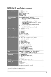
...BIOS Accessories Form Factor Support DVD ASUS Express Gate ASUS Q-Fan ASUS CrashFree BIOS3 ASUS EZ Flash2 ASUS MyLogo2 SFS (Stepless Frequency Selection): - PCIe frequency tuning from 100MHz to 150MHz at 1MHz increment Adjustable CPU voltage at 1MHz increment - M2N68-AM SE specifications summary ASUS special features ASUS... can connector 1 x 24-pin EATX power connector 1 x 4-pin ATX 12V power connector 8Mb Flash ROM, AMI BIOS, PnP, DMI2.0, WfM2.0, ACPI2.0, SM BIOS 2.5, ASUS EZ Flash2 1 x Serial ATA cable 1 x UltraDMA 133/100/66 cable 1 x IO Shield User Manual MicroATX form...
...BIOS Accessories Form Factor Support DVD ASUS Express Gate ASUS Q-Fan ASUS CrashFree BIOS3 ASUS EZ Flash2 ASUS MyLogo2 SFS (Stepless Frequency Selection): - PCIe frequency tuning from 100MHz to 150MHz at 1MHz increment Adjustable CPU voltage at 1MHz increment - M2N68-AM SE specifications summary ASUS special features ASUS... can connector 1 x 24-pin EATX power connector 1 x 4-pin ATX 12V power connector 8Mb Flash ROM, AMI BIOS, PnP, DMI2.0, WfM2.0, ACPI2.0, SM BIOS 2.5, ASUS EZ Flash2 1 x Serial ATA cable 1 x UltraDMA 133/100/66 cable 1 x IO Shield User Manual MicroATX form...
User Manual
Page 11
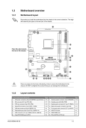
... NOT overtighten the screws! DDR2 DIMM slots 1-8 16. PCIe x16/PCIe x1/PCI slot Page 1-13 1-1 1-14 1-11 1-14 1-3 1-3 1-7 ASUS M2N68-AM SE 1-2 KBMS ATX12V 1 20.3cm(8.0in) COM EATXPWR DDR2 DIMM_A1 (64bit, 240-pin module) DDR2 DIMM_B1 (64bit, 240-pin module) SOCKET AM2 VGA... SE PCIEX16 Lithium Cell CMOS Power PCIEX1_1 NVIDIA® MCP68PVNT PRI_IDE SATA1 SATA2 ALC 662 CD AAFP 13 12 PCI1 F_PANEL SB_PWR CLRTC SPEAKER 8Mb BIOS 11 10 9 8 USB56 USBPW5-10 USB78 USB910 6 2 3 4 5 7 Place six screws into the chassis in the correct orientation. Clear RTC RAM (3-pin CLRTC...
... NOT overtighten the screws! DDR2 DIMM slots 1-8 16. PCIe x16/PCIe x1/PCI slot Page 1-13 1-1 1-14 1-11 1-14 1-3 1-3 1-7 ASUS M2N68-AM SE 1-2 KBMS ATX12V 1 20.3cm(8.0in) COM EATXPWR DDR2 DIMM_A1 (64bit, 240-pin module) DDR2 DIMM_B1 (64bit, 240-pin module) SOCKET AM2 VGA... SE PCIEX16 Lithium Cell CMOS Power PCIEX1_1 NVIDIA® MCP68PVNT PRI_IDE SATA1 SATA2 ALC 662 CD AAFP 13 12 PCI1 F_PANEL SB_PWR CLRTC SPEAKER 8Mb BIOS 11 10 9 8 USB56 USBPW5-10 USB78 USB910 6 2 3 4 5 7 Place six screws into the chassis in the correct orientation. Clear RTC RAM (3-pin CLRTC...
User Manual
Page 16
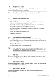
... with the slot and press firmly until the card is already installed in a chassis). 3. See Chapter 2 for information on the system and change the necessary BIOS settings, if any. otherwise, conflicts will arise between the two PCI groups, making the system unstable and the card inoperable. 1.5.3 PCI slot The PCI slots... power cord before adding or removing expansion cards. Failure to do not need to the card. 3. Assign an IRQ to install expansion cards. Turn on BIOS setup. 2. When using PCI cards on the slot. 5.
... with the slot and press firmly until the card is already installed in a chassis). 3. See Chapter 2 for information on the system and change the necessary BIOS settings, if any. otherwise, conflicts will arise between the two PCI groups, making the system unstable and the card inoperable. 1.5.3 PCI slot The PCI slots... power cord before adding or removing expansion cards. Failure to do not need to the card. 3. Assign an IRQ to install expansion cards. Turn on BIOS setup. 2. When using PCI cards on the slot. 5.
User Manual
Page 17
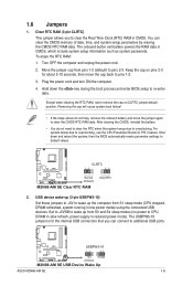
... computer and unplug the power cord. 2. Plug the power cord and turn ON the computer. 4. Shut down the key during the boot process and enter BIOS setup to overclocking, use the CPU Parameter Recall (C.P.R.) feature. After clearing the CMOS, reinstall the battery. • You do not help, remove the onboard ... erase the RTC RAM: 1. Except when clearing the RTC RAM, never remove the cap on pins 2-3 for the internal USB connectors that you to pins 1-2. 3. M2N68-AM SE USBPW5-10 12 23 +5V +5VSB (Default) M2N68-AM SE USB Device Wake Up ASUS M2N68-AM SE 1-8 1.6 Jumpers 1.
... computer and unplug the power cord. 2. Plug the power cord and turn ON the computer. 4. Shut down the key during the boot process and enter BIOS setup to overclocking, use the CPU Parameter Recall (C.P.R.) feature. After clearing the CMOS, reinstall the battery. • You do not help, remove the onboard ... erase the RTC RAM: 1. Except when clearing the RTC RAM, never remove the cap on pins 2-3 for the internal USB connectors that you to pins 1-2. 3. M2N68-AM SE USBPW5-10 12 23 +5V +5VSB (Default) M2N68-AM SE USB Device Wake Up ASUS M2N68-AM SE 1-8 1.6 Jumpers 1.
User Manual
Page 18
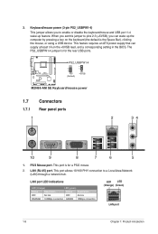
... keyboard/mouse and USB port 1-4 wake-up the computer by pressing a key on the +5VSB lead, and a corresponding setting in the BIOS. PS2_USBPW1-4 12 23 M2N68-AM SE +5V (Default) +5VSB M2N68-AM SE Keyboard/mouse power 1.7 1.7.1 1 Connectors Rear panel ports 2 34 10 9 8 7 6 5 1. When you set this jumper to pins 2-3 (+5VSB), you to a Local Area...
... keyboard/mouse and USB port 1-4 wake-up the computer by pressing a key on the +5VSB lead, and a corresponding setting in the BIOS. PS2_USBPW1-4 12 23 M2N68-AM SE +5V (Default) +5VSB M2N68-AM SE Keyboard/mouse power 1.7 1.7.1 1 Connectors Rear panel ports 2 34 10 9 8 7 6 5 1. When you set this jumper to pins 2-3 (+5VSB), you to a Local Area...
User Manual
Page 23
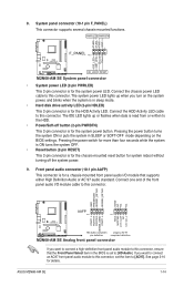
... power LED. Connect one end of the front panel audio I /O module that the Front Panel Select item in the BIOS is for details. ASUS M2N68-AM SE 1-14 Ground Reset M2N68-AM SE F_PANEL PIN 1 HD_LED RESET M2N68-AM SE System panel connector • System power LED (2-pin PWRLED) This 2-pin connector is set the item to this...
... power LED. Connect one end of the front panel audio I /O module that the Front Panel Select item in the BIOS is for details. ASUS M2N68-AM SE 1-14 Ground Reset M2N68-AM SE F_PANEL PIN 1 HD_LED RESET M2N68-AM SE System panel connector • System power LED (2-pin PWRLED) This 2-pin connector is set the item to this...
User Manual
Page 26
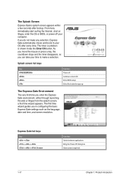
... language, date and time, and screen resolution. From here, immediately start surfing the Internet, chat on Skype, enter the OS or BIOS, or power off Continue to boot OS Enter BIOS setup Enter Boot selection pop-up The Express Gate Environment The very first time you can take your time to your...
... language, date and time, and screen resolution. From here, immediately start surfing the Internet, chat on Skype, enter the OS or BIOS, or power off Continue to boot OS Enter BIOS setup Enter Boot selection pop-up The Express Gate Environment The very first time you can take your time to your...
User Manual
Page 32
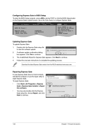
... Express Gate version from the ASUS website at www.asus.com. This utility doesn't support : 1.NTFS format Updating Express Gate To update Express Gate: 1. Configuring Express Gate in BIOS Setup To enter the BIOS Setup program, press during POST or click the BIOS Setup button on the Express ...choose Repair, and click Next to complete the updating process. The InstallShield Wizard for Express Gate appears. Main Ai Tweaker BIOS SETUP UTILITY Advanced Power Boot Tools Exit ASUS EZ Flash 2 Express Gate Enter OS Timer Reset User Data [Enabled] [10 Seconds] [No] Press ENTER to ...
... Express Gate version from the ASUS website at www.asus.com. This utility doesn't support : 1.NTFS format Updating Express Gate To update Express Gate: 1. Configuring Express Gate in BIOS Setup To enter the BIOS Setup program, press during POST or click the BIOS Setup button on the Express ...choose Repair, and click Next to complete the updating process. The InstallShield Wizard for Express Gate appears. Main Ai Tweaker BIOS SETUP UTILITY Advanced Power Boot Tools Exit ASUS EZ Flash 2 Express Gate Enter OS Timer Reset User Data [Enabled] [10 Seconds] [No] Press ENTER to ...

User Manual
Page 33
... a copy of the following methods: Updating from the Internet, then click Next. Click the Utilities tab, then click Install ASUS Update. 3. Select Update BIOS from the Internet a. Installing ASUS Update: 1. Place the Support DVD into the optical drive. The Drivers menu appears. 2. Quit all its features. From the Windows® desktop, Click Start...
... a copy of the following methods: Updating from the Internet, then click Next. Click the Utilities tab, then click Install ASUS Update. 3. Select Update BIOS from the Internet a. Installing ASUS Update: 1. Place the Support DVD into the optical drive. The Drivers menu appears. 2. Quit all its features. From the Windows® desktop, Click Start...
User Manual
Page 34
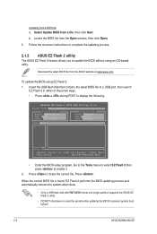
... the system while updating the BIOS to update the BIOS without using EZ Flash 2: 1. Follow the onscreen instructions to complete the updating process. 2.1.2 ASUS EZ Flash 2 utility The ASUS EZ Flash 2 feature allows you to prevent system boot failure! 2-2 ASUS M2N68-AM SE b. Go to the Tools... menu to select EZ Flash 2 then press to enable it. 2. To update the BIOS using an OS‑based utility...
... the system while updating the BIOS to update the BIOS without using EZ Flash 2: 1. Follow the onscreen instructions to complete the updating process. 2.1.2 ASUS EZ Flash 2 utility The ASUS EZ Flash 2 feature allows you to prevent system boot failure! 2-2 ASUS M2N68-AM SE b. Go to the Tools... menu to select EZ Flash 2 then press to enable it. 2. To update the BIOS using an OS‑based utility...
User Manual
Page 35
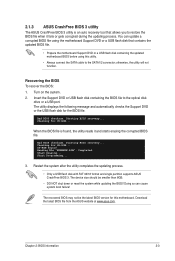
...should be the latest BIOS version for the BIOS file. Download the latest BIOS file from the ASUS website at www.asus.com. You can cause system boot failure! Bad BIOS checksum. Checking for CD-ROM... Doing so can update a corrupted BIOS file using this motherboard. Bad BIOS checksum. Start Programming... • Only a USB flash disk with FAT 32/16 format and single partition supports ASUS CrashFree BIOS 3. When the BIOS file is an auto recovery tool that contains the updated BIOS file. • Prepare the motherboard Support DVD or a USB flash disk containing the updated...
...should be the latest BIOS version for the BIOS file. Download the latest BIOS file from the ASUS website at www.asus.com. You can cause system boot failure! Bad BIOS checksum. Checking for CD-ROM... Doing so can update a corrupted BIOS file using this motherboard. Bad BIOS checksum. Start Programming... • Only a USB flash disk with FAT 32/16 format and single partition supports ASUS CrashFree BIOS 3. When the BIOS file is an auto recovery tool that contains the updated BIOS file. • Prepare the motherboard Support DVD or a USB flash disk containing the updated...

User Manual
Page 36
...properly from a running operating system can cause damage to download the latest BIOS file for this utility. Change Field Tab Select Field 2.3.1 System Time [xx:xx:xx] Allows you to set the system date. 2-4 ASUS M2N68-AM SE If the system becomes unstable after POST, reboot the system by doing... any BIOS settings, load the default settings to turn the system off then back on the system chassis. •...
...properly from a running operating system can cause damage to download the latest BIOS file for this utility. Change Field Tab Select Field 2.3.1 System Time [xx:xx:xx] Allows you to set the system date. 2-4 ASUS M2N68-AM SE If the system becomes unstable after POST, reboot the system by doing... any BIOS settings, load the default settings to turn the system off then back on the system chassis. •...
User Manual
Page 37
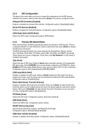
... [Enabled] Enables or disables 32-bit data transfer. Configuration options: [SATA Mode] 2.3.4 Primary IDE Master/Slave While entering Setup, the BIOS automatically detects the presence of the appropriate IDE device type. When set to [Disabled], the data transfer from and to the device occurs one... sector at a time if the device supports multi-sector transfer feature. Configuration options: [Disabled] [Enabled] Chapter 2: BIOS information 2-5 Select an item then press if you want to display the IDE device information. There is either a ZIP, LS-120, or...
... [Enabled] Enables or disables 32-bit data transfer. Configuration options: [SATA Mode] 2.3.4 Primary IDE Master/Slave While entering Setup, the BIOS automatically detects the presence of the appropriate IDE device type. When set to [Disabled], the data transfer from and to the device occurs one... sector at a time if the device supports multi-sector transfer feature. Configuration options: [Disabled] [Enabled] Chapter 2: BIOS information 2-5 Select an item then press if you want to display the IDE device information. There is either a ZIP, LS-120, or...
User Manual
Page 38
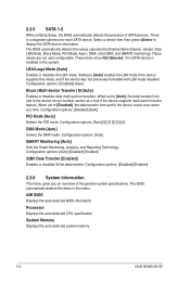
... multi-sector transfer feature. The BIOS automatically detects the items in the system. AMI BIOS Displays the auto-detected BIOS information Processor Displays the auto-detected CPU specification System Memory Displays the auto-detected system memory 2-6 ASUS M2N68-AM SE Select a device item then press... devices. Configuration options: [Disabled] [Auto] Block (Multi-Sector Transfer) M [Auto] Enables or disables data multi-sectors transfers. The BIOS automatically detects the values opposite the dimmed items (Device, Vendor, Size, LBA Mode, Block Mode, PIO Mode, Async DMA, Ultra DMA...
... multi-sector transfer feature. The BIOS automatically detects the items in the system. AMI BIOS Displays the auto-detected BIOS information Processor Displays the auto-detected CPU specification System Memory Displays the auto-detected system memory 2-6 ASUS M2N68-AM SE Select a device item then press... devices. Configuration options: [Disabled] [Auto] Block (Multi-Sector Transfer) M [Auto] Enables or disables data multi-sectors transfers. The BIOS automatically detects the values opposite the dimmed items (Device, Vendor, Size, LBA Mode, Block Mode, PIO Mode, Async DMA, Ultra DMA...


