User Manual
Page 3
... Unit (CPU 1-3 1.4 System memory 1-3 1.4.1 Overview 1-3 1.4.2 Memory configurations 1-4 1.5 Expansion slots 1-7 1.5.1 Installing an expansion card 1-7 1.5.2 Configuring an expansion card 1-7 1.5.3 PCI slot 1-7 1.5.4 PCI Express x1 slot 1-7 1.5.5 PCI Express x16 slot 1-7 1.6 Jumpers 1-8 1.7 Connectors 1-9 1.7.1 Rear panel ports 1-9 1.7.2 Internal connectors 1-10 1.8 Software support 1-15 1.8.1 Installing an operating system 1-15 1.8.2 Support DVD information 1-15 1.8.3 ASUS Express Gate 1-16 Chapter 2: BIOS information 2.1 Managing and updating your BIOS 2-1 2.1.1 ASUS Update...
... Unit (CPU 1-3 1.4 System memory 1-3 1.4.1 Overview 1-3 1.4.2 Memory configurations 1-4 1.5 Expansion slots 1-7 1.5.1 Installing an expansion card 1-7 1.5.2 Configuring an expansion card 1-7 1.5.3 PCI slot 1-7 1.5.4 PCI Express x1 slot 1-7 1.5.5 PCI Express x16 slot 1-7 1.6 Jumpers 1-8 1.7 Connectors 1-9 1.7.1 Rear panel ports 1-9 1.7.2 Internal connectors 1-10 1.8 Software support 1-15 1.8.1 Installing an operating system 1-15 1.8.2 Support DVD information 1-15 1.8.3 ASUS Express Gate 1-16 Chapter 2: BIOS information 2.1 Managing and updating your BIOS 2-1 2.1.1 ASUS Update...
User Manual
Page 8
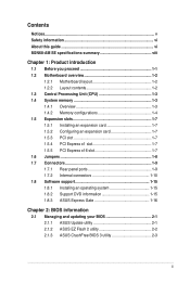
... if you install a total memory of 256MB Supports RGB with max. Integrated NVIDIA® GeForce 7 Series Shader model 3.0 DirectX 9 graphics processor Maximum shared memory of 4GB or more, Windows® 32-bit operating system may only recognize less than 3GB is supported per channel. M2N68-AM SE specifications summary CPU Chipset System bus Memory Graphics Expansion slots Storage Audio USB LAN AMD® Socket AM2+ / AM2 for the latest Memory QVL (Qualified Vendors List). *** When you are using a Windows 32-bit operating system...
... if you install a total memory of 256MB Supports RGB with max. Integrated NVIDIA® GeForce 7 Series Shader model 3.0 DirectX 9 graphics processor Maximum shared memory of 4GB or more, Windows® 32-bit operating system may only recognize less than 3GB is supported per channel. M2N68-AM SE specifications summary CPU Chipset System bus Memory Graphics Expansion slots Storage Audio USB LAN AMD® Socket AM2+ / AM2 for the latest Memory QVL (Qualified Vendors List). *** When you are using a Windows 32-bit operating system...
User Manual
Page 11
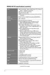
..., 4-pin ATX12V) 2. USB device wake-up (3-pin USBPW 5-10) 6. Keyboard/mouse power (3-pin PS2_USBPW 1-4) 7. Front panel audio connector (10-1 pin AAFP) 1-9 14. The edge with external ports goes to the chassis. Doing so can damage the motherboard. 1.2.2 Layout contents Connectors/Jumpers/Slots/LED 1. Standby power LED (SB_PWR) 1-12 11. AM2 CPU Socket 1-12 15. PCIe x16/PCIe x1/PCI slot Page 1-13 1-1 1-14 1-11 1-14 1-3 1-3 1-7 ASUS M2N68-AM SE 1-2 Serial ATA connectors (7-pin SATA1, SATA2) 5. CPU fan connector (4-pin CPU_FAN) 4. Internal speaker connector (4-pin SPEAKER...
..., 4-pin ATX12V) 2. USB device wake-up (3-pin USBPW 5-10) 6. Keyboard/mouse power (3-pin PS2_USBPW 1-4) 7. Front panel audio connector (10-1 pin AAFP) 1-9 14. The edge with external ports goes to the chassis. Doing so can damage the motherboard. 1.2.2 Layout contents Connectors/Jumpers/Slots/LED 1. Standby power LED (SB_PWR) 1-12 11. AM2 CPU Socket 1-12 15. PCIe x16/PCIe x1/PCI slot Page 1-13 1-1 1-14 1-11 1-14 1-3 1-3 1-7 ASUS M2N68-AM SE 1-2 Serial ATA connectors (7-pin SATA1, SATA2) 5. CPU fan connector (4-pin CPU_FAN) 4. Internal speaker connector (4-pin SPEAKER...
User Manual
Page 13
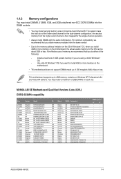
... using a 32-bit Windows® OS. - You may install varying memory sizes in Channel A and Channel B. Install a maximum of 3GB system memory if you do either of the following: - Use a 64-bit Windows® OS if you install 4GB or more memory on the motherboard. • This motherboard does not support DIMMs made up to install 4GB or more memory on the motherboard, the actual usable memory for the dual-channel configuration. M2N68-AM SE Motherboard Qualified Vendors Lists...
... using a 32-bit Windows® OS. - You may install varying memory sizes in Channel A and Channel B. Install a maximum of 3GB system memory if you do either of the following: - Use a 64-bit Windows® OS if you install 4GB or more memory on the motherboard. • This motherboard does not support DIMMs made up to install 4GB or more memory on the motherboard, the actual usable memory for the dual-channel configuration. M2N68-AM SE Motherboard Qualified Vendors Lists...
User Manual
Page 16
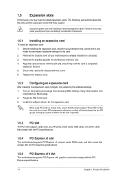
.... 1.5.4 PCI Express x1 slot This motherboard supports PCI Express x1 network cards, SCSI cards, and other cards that comply with the PCI Express specifications. 1.5.5 PCI Express x16 slot This motherboard supports PCI Express x16 graphics cards that they support. Failure to use. 4. Align the card connector with it by adjusting the software settings. 1. Unplug the power cord before adding or removing expansion cards. Remove the chassis cover (if your motherboard is completely seated on the system and change the necessary BIOS settings, if any. Install the software drivers for...
.... 1.5.4 PCI Express x1 slot This motherboard supports PCI Express x1 network cards, SCSI cards, and other cards that comply with the PCI Express specifications. 1.5.5 PCI Express x16 slot This motherboard supports PCI Express x16 graphics cards that they support. Failure to use. 4. Align the card connector with it by adjusting the software settings. 1. Unplug the power cord before adding or removing expansion cards. Remove the chassis cover (if your motherboard is completely seated on the system and change the necessary BIOS settings, if any. Install the software drivers for...
User Manual
Page 17
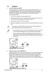
..., then the BIOS automatically resets parameter settings to pins 2-3. Keep the cap on CLRTC jumper default position. M2N68-AM SE USBPW5-10 12 23 +5V +5VSB (Default) M2N68-AM SE USB Device Wake Up ASUS M2N68-AM SE 1-8 After clearing the CMOS, reinstall the battery. • You do not help, remove the onboard battery and move the cap back to CPU, DRAM in slow refresh, power supply in CMOS, which include system setup information such as system passwords. The USBPW5...
..., then the BIOS automatically resets parameter settings to pins 2-3. Keep the cap on CLRTC jumper default position. M2N68-AM SE USBPW5-10 12 23 +5V +5VSB (Default) M2N68-AM SE USB Device Wake Up ASUS M2N68-AM SE 1-8 After clearing the CMOS, reinstall the battery. • You do not help, remove the onboard battery and move the cap back to CPU, DRAM in slow refresh, power supply in CMOS, which include system setup information such as system passwords. The USBPW5...
User Manual
Page 19
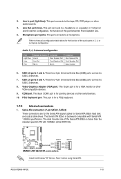
... keyboard. 1.7.2 Internal connectors 1. USB 2.0 ports 3 and 4. This 15-pin port is faster than the standard parallel ATA with Serial ATA 1.5Gb/s specification. In 4-channel and 6-channel configuration, the function of the audio ports in 2, 4, or 6-channel configuration. These two 4-pin Universal Serial Bus (USB) ports connect to USB 2.0 devices. 7. Video Graphics Adapter (VGA) port. COM port. Serial ATA connectors (7-pin SATA1, SATA2) These connectors are for the Serial ATA signal cables for the function of this port becomes Front Speaker Out. 5. Line Out port (lime). ASUS M2N68...
... keyboard. 1.7.2 Internal connectors 1. USB 2.0 ports 3 and 4. This 15-pin port is faster than the standard parallel ATA with Serial ATA 1.5Gb/s specification. In 4-channel and 6-channel configuration, the function of the audio ports in 2, 4, or 6-channel configuration. These two 4-pin Universal Serial Bus (USB) ports connect to USB 2.0 devices. 7. Video Graphics Adapter (VGA) port. COM port. Serial ATA connectors (7-pin SATA1, SATA2) These connectors are for the Serial ATA signal cables for the function of this port becomes Front Speaker Out. 5. Line Out port (lime). ASUS M2N68...
User Manual
Page 23
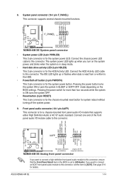
... this connector. Connect the chassis power LED cable to this connector, set to this connector, ensure that supports either High Definition Audio or AC`97 audio standard. Connect the HDD Activity LED cable to [HD Audio]. See page 2-10 for the system power LED. Pressing the power button turns the system ON or puts the system in sleep mode. • Hard disk drive activity LED (2-pin HDLED) This 2-pin connector is for the HDD Activity LED. Ground Reset M2N68-AM SE F_PANEL PIN 1 HD_LED RESET M2N68-AM SE System panel connector • System power LED (2-pin...
... this connector. Connect the chassis power LED cable to this connector, set to this connector, ensure that supports either High Definition Audio or AC`97 audio standard. Connect the HDD Activity LED cable to [HD Audio]. See page 2-10 for the system power LED. Pressing the power button turns the system ON or puts the system in sleep mode. • Hard disk drive activity LED (2-pin HDLED) This 2-pin connector is for the HDD Activity LED. Ground Reset M2N68-AM SE F_PANEL PIN 1 HD_LED RESET M2N68-AM SE System panel connector • System power LED (2-pin...
User Manual
Page 25
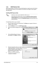
... motherboard chipset-controlled onboard SATA ports only. Follow the onscreen instructions to continue. 5. Click the Utilities tab, then click ASUS Express Gate. 3. The InstallShield Wizard for the exact location of the onboard SATA ports. The Drivers menu appears if Autorun is enabled on environment that gives you have multiple partitions installed on your computer: 1. Select your computer, it is recommended to install Express Gate in IDE mode only. • ASUS Express Gate supports HDDs connected to continue. 6. 1.8.3 ASUS Express...
... motherboard chipset-controlled onboard SATA ports only. Follow the onscreen instructions to continue. 5. Click the Utilities tab, then click ASUS Express Gate. 3. The InstallShield Wizard for the exact location of the onboard SATA ports. The Drivers menu appears if Autorun is enabled on environment that gives you have multiple partitions installed on your computer: 1. Select your computer, it is recommended to install Express Gate in IDE mode only. • ASUS Express Gate supports HDDs connected to continue. 6. 1.8.3 ASUS Express...
User Manual
Page 31
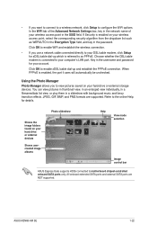
... the network name of your hard drive or external devices Shows usercreated image albums Photo slideshow Help View mode selection Image control bar ASUS Express Gate supports HDDs connected to as WEPAUTO in the Encryption Type field, and key in the username and password for details. Using the Photo Manager Photo Manager allows you to configure the WiFi options. Refer to your computer's LAN port. Click OK to enable xDSL/cable...
... the network name of your hard drive or external devices Shows usercreated image albums Photo slideshow Help View mode selection Image control bar ASUS Express Gate supports HDDs connected to as WEPAUTO in the Encryption Type field, and key in the username and password for details. Using the Photo Manager Photo Manager allows you to configure the WiFi options. Refer to your computer's LAN port. Click OK to enable xDSL/cable...
User Manual
Page 32
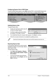
... BIOS Setup To enter the BIOS Setup program, press during POST or click the BIOS Setup button on the Express Gate's splash screen. A software update confirmation dialog box appears. To repair Express Gate: • Click Start > All Programs > Express Gate > Express Gate Installer > Repair this software. • You may also double-click the Express Gate setup file, choose Repair, and click Next to complete the updating process. Main Ai Tweaker BIOS SETUP UTILITY Advanced Power Boot Tools Exit ASUS EZ Flash 2 Express Gate Enter OS Timer Reset User...
... BIOS Setup To enter the BIOS Setup program, press during POST or click the BIOS Setup button on the Express Gate's splash screen. A software update confirmation dialog box appears. To repair Express Gate: • Click Start > All Programs > Express Gate > Express Gate Installer > Repair this software. • You may also double-click the Express Gate setup file, choose Repair, and click Next to complete the updating process. Main Ai Tweaker BIOS SETUP UTILITY Advanced Power Boot Tools Exit ASUS EZ Flash 2 Express Gate Enter OS Timer Reset User...

User Manual
Page 33
... a network or an Internet Service Provider (ISP). • This utility is a utility that comes with the motherboard package. Copy the original motherboard BIOS using the ASUS Update utility. 2.1.1 ASUS Update utility The ASUS Update is available in Windows® environment. • ASUS Update requires an Internet connection either of the original motherboard BIOS file to a USB flash disk in case you need to manage, save, and update the motherboard BIOS in the Support DVD that allows you update the BIOS using this utility. Installing ASUS Update: 1. Always update the utility to...
... a network or an Internet Service Provider (ISP). • This utility is a utility that comes with the motherboard package. Copy the original motherboard BIOS using the ASUS Update utility. 2.1.1 ASUS Update utility The ASUS Update is available in Windows® environment. • ASUS Update requires an Internet connection either of the original motherboard BIOS file to a USB flash disk in case you need to manage, save, and update the motherboard BIOS in the Support DVD that allows you update the BIOS using this utility. Installing ASUS Update: 1. Always update the utility to...
User Manual
Page 34
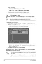
... updating the BIOS to enable it. 2. Press . To update the BIOS using an OS‑based utility. Insert the USB flash disk that contains the latest BIOS file to a USB port, then launch EZ Flash 2 in either of these two ways. • Press + during POST to locate the correct file. Press to display the following: ASUSTek EZ Flash 2 BIOS ROM Utility V3.06 FLASH TYPE: MXIC 25L8005 Current ROM BOARD: M2N68-AM SE VER: 0203 DATE: 10/20/2008 Update ROM BOARD...
... updating the BIOS to enable it. 2. Press . To update the BIOS using an OS‑based utility. Insert the USB flash disk that contains the latest BIOS file to a USB port, then launch EZ Flash 2 in either of these two ways. • Press + during POST to locate the correct file. Press to display the following: ASUSTek EZ Flash 2 BIOS ROM Utility V3.06 FLASH TYPE: MXIC 25L8005 Current ROM BOARD: M2N68-AM SE VER: 0203 DATE: 10/20/2008 Update ROM BOARD...
User Manual
Page 37
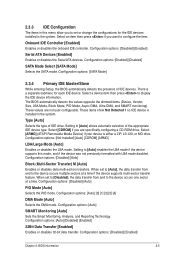
...and SMART monitoring). These values are specifically configuring a CD-ROM drive. Configuration options: [Disabled] [Auto] Block (Multi-Sector Transfer) M [Auto] Enables or disables data multi-sectors transfers. Configuration options: [Disabled] [Auto] PIO Mode [Auto] Selects the PIO mode. Configuration options: [SATA Mode] 2.3.4 Primary IDE Master/Slave While entering Setup, the BIOS automatically detects the presence of IDE drive. When set or change the configurations for each IDE device. Configuration options: [Auto] [Disabled] [Enabled] 32Bit Data Transfer [Enabled] Enables or...
...and SMART monitoring). These values are specifically configuring a CD-ROM drive. Configuration options: [Disabled] [Auto] Block (Multi-Sector Transfer) M [Auto] Enables or disables data multi-sectors transfers. Configuration options: [Disabled] [Auto] PIO Mode [Auto] Selects the PIO mode. Configuration options: [SATA Mode] 2.3.4 Primary IDE Master/Slave While entering Setup, the BIOS automatically detects the presence of IDE drive. When set or change the configurations for each IDE device. Configuration options: [Auto] [Disabled] [Enabled] 32Bit Data Transfer [Enabled] Enables or...
User Manual
Page 38
...time if the device supports multi-sector transfer feature. AMI BIOS Displays the auto-detected BIOS information Processor Displays the auto-detected CPU specification System Memory Displays the auto-detected system memory 2-6 ASUS M2N68-AM SE The BIOS automatically detects the values opposite the dimmed items (Device, Vendor, Size, LBA Mode, Block Mode, PIO Mode, Async DMA, Ultra DMA, and SMART monitoring). Configuration options: [Auto] SMART Monitoring [Auto] Sets the Smart Monitoring, Analysis, and Reporting Technology. Configuration options: [Disabled] [Auto] Block (Multi-Sector...
...time if the device supports multi-sector transfer feature. AMI BIOS Displays the auto-detected BIOS information Processor Displays the auto-detected CPU specification System Memory Displays the auto-detected system memory 2-6 ASUS M2N68-AM SE The BIOS automatically detects the values opposite the dimmed items (Device, Vendor, Size, LBA Mode, Block Mode, PIO Mode, Async DMA, Ultra DMA, and SMART monitoring). Configuration options: [Auto] SMART Monitoring [Auto] Sets the Smart Monitoring, Analysis, and Reporting Technology. Configuration options: [Disabled] [Auto] Block (Multi-Sector...
User Manual
Page 39
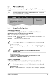
...Power BIOS SETUP UTILITY Boot Tools Exit JumperFree Configuration CPU Configuration Chipset Onboard Devices Configuration PCIPnP USB Configuration Adjust System Frequency etc. 2.4.1 JumperFree Configuration CPU Overclocking [Auto] Selects the CPU overclocking options to set the PCIE frequency. Loads the optimal settings for stability when overclocking. [Standard] - Configuration options: [200.0] [201.0] - [299.0] [300.0] The following item appears only when the CPU Overclocking item is set the CPU frequency. PCIE Frequency [100] Allows you to achieve desired CPU internal frequency...
...Power BIOS SETUP UTILITY Boot Tools Exit JumperFree Configuration CPU Configuration Chipset Onboard Devices Configuration PCIPnP USB Configuration Adjust System Frequency etc. 2.4.1 JumperFree Configuration CPU Overclocking [Auto] Selects the CPU overclocking options to set the PCIE frequency. Loads the optimal settings for stability when overclocking. [Standard] - Configuration options: [200.0] [201.0] - [299.0] [300.0] The following item appears only when the CPU Overclocking item is set the CPU frequency. PCIE Frequency [100] Allows you to achieve desired CPU internal frequency...
User Manual
Page 41
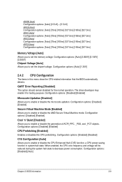
GART Error Reporting [Disabled] This option should remain disabled for testing purpose. Configuration options: [Disabled] [Enabled] Secure Virtual Machine Mode [Enabled] Allows you to enable or disable the generation of ACPI_PPC, _PSS, and _PCT objects. The driver developer may enable it for the normal operation. Configuration options: [Disabled] [Enabled] Cool 'n' Quiet [Disabled] Allows you to enable or disable the AMD Secure Virtual Machine mode. Configuration options: [Disabled] [Auto] Chapter 2: BIOS information 2-9 Configuration options: [Disabled] [Enabled] ...
GART Error Reporting [Disabled] This option should remain disabled for testing purpose. Configuration options: [Disabled] [Enabled] Secure Virtual Machine Mode [Enabled] Allows you to enable or disable the generation of ACPI_PPC, _PSS, and _PCT objects. The driver developer may enable it for the normal operation. Configuration options: [Disabled] [Enabled] Cool 'n' Quiet [Disabled] Allows you to enable or disable the AMD Secure Virtual Machine mode. Configuration options: [Disabled] [Auto] Chapter 2: BIOS information 2-9 Configuration options: [Disabled] [Enabled] ...
User Manual
Page 42
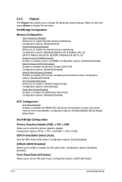
...] Allows you to change the advanced chipset settings. Configuration options: [Disabled] [Address bits 6] [Address bits 12] [XOR of Address bits [20:16, 6]] [XOR of Address bits [20:16, 9]] Enable Clock to All DIMMs [Disabled] Enables or disables clock to select the primary graphics adapter. 2.4.3 Chipset The Chipset menu allows you to enable the bank memory interleaving. Configuration options: [AC97] [HD Audio] 2-10 ASUS M2N68-AM SE Configuration options: [Disabled] [Basic] [Good] [Super] [Max] [User] SouthBridge Configuration Primary Graphics Adapter [PCIE -> PCI -> IGP] Allows you...
...] Allows you to change the advanced chipset settings. Configuration options: [Disabled] [Address bits 6] [Address bits 12] [XOR of Address bits [20:16, 6]] [XOR of Address bits [20:16, 9]] Enable Clock to All DIMMs [Disabled] Enables or disables clock to select the primary graphics adapter. 2.4.3 Chipset The Chipset menu allows you to enable the bank memory interleaving. Configuration options: [AC97] [HD Audio] 2-10 ASUS M2N68-AM SE Configuration options: [Disabled] [Basic] [Good] [Super] [Max] [User] SouthBridge Configuration Primary Graphics Adapter [PCIE -> PCI -> IGP] Allows you...
User Manual
Page 44
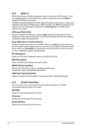
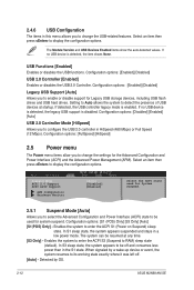
... a wake-up device or event, the system resumes to enable or disable support for Legacy USB storage devices, including USB flash drives and USB hard drives. Configuration options: [Enabled] [Disabled] Legacy USB Support [Auto] Allows you to its working state exactly where it was left off and consumes less power than in the S1 state. If no USB device is detected, the item shows None. When signaled by OS. 2-12 ASUS M2N68-AM SE Configuration options: [Disabled] [Enabled] [Auto] USB 2.0 Controller Mode [HiSpeed] Allows you to display the configuration options. Setting to Auto...
... a wake-up device or event, the system resumes to enable or disable support for Legacy USB storage devices, including USB flash drives and USB hard drives. Configuration options: [Enabled] [Disabled] Legacy USB Support [Auto] Allows you to its working state exactly where it was left off and consumes less power than in the S1 state. If no USB device is detected, the item shows None. When signaled by OS. 2-12 ASUS M2N68-AM SE Configuration options: [Disabled] [Enabled] [Auto] USB 2.0 Controller Mode [HiSpeed] Allows you to display the configuration options. Setting to Auto...
User Manual
Page 46
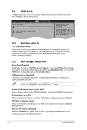
...Main Advanced Boot Settings Power Boot Device Priority BIOS SETUP UTILITY Boot Tools Exit Boot Settings Configuration Security Specifies the Boot Device Priority sequence. The number of devices installed in the system. Configuration options: [Removable Device] [Hard Drive] [ATAPI CD-ROM ] [Disabled] 2.6.2 Boot Settings Configuration Quick Boot [Enabled] Enabling this item to [Enabled] to use the ASUS MyLogo 2™ feature. Configuration options: [Off] [On] PS/2 Mouse Support [Auto] Allows you to enable or disable the full screen logo display feature. A virtual floppy disk drive...
...Main Advanced Boot Settings Power Boot Device Priority BIOS SETUP UTILITY Boot Tools Exit Boot Settings Configuration Security Specifies the Boot Device Priority sequence. The number of devices installed in the system. Configuration options: [Removable Device] [Hard Drive] [ATAPI CD-ROM ] [Disabled] 2.6.2 Boot Settings Configuration Quick Boot [Enabled] Enabling this item to [Enabled] to use the ASUS MyLogo 2™ feature. Configuration options: [Off] [On] PS/2 Mouse Support [Auto] Allows you to enable or disable the full screen logo display feature. A virtual floppy disk drive...


