
User Manual
Page 1
Motherboard
Motherboard
User Manual
Page 7
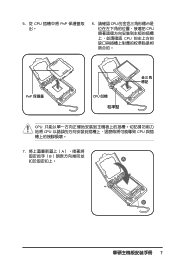
5. 從 CPU PnP 6. 請確認 CPU CPU CPU PnP 保護蓋 CPU CPU CPU CPU 7 A B A B
5. 從 CPU PnP 6. 請確認 CPU CPU CPU PnP 保護蓋 CPU CPU CPU CPU 7 A B A B
User Manual
Page 25
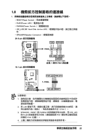
Ground Reset PWR LED PWR BTN M2N-X F_PANEL HD LED RESET 1 2. 若 LED PIN1)。 3. SPEAKER、RESET 與 PWRSW IDE_LED 與 PLED PIN1 PIN1 4 25 PWR Ground Reset Ground 10-1 pin IDE_LED RESET PWRSW * Requires an ATX power supply. 紅色 1 表示 PIN1 的位置 PLED+ PLEDPWR GND IDELED+ IDELED- 1.8 1 RESET(Reset Switch PLED(Power LED PWRSW(Power Switch IDE_LED(IDE Hard Disk Active LED SPEAKER(Speaker Connector 20-8 pin PLED SPEAKER 1 PANEL1 PLED+ PLED+5V Ground Ground Speaker P5B-E ® ...
Ground Reset PWR LED PWR BTN M2N-X F_PANEL HD LED RESET 1 2. 若 LED PIN1)。 3. SPEAKER、RESET 與 PWRSW IDE_LED 與 PLED PIN1 PIN1 4 25 PWR Ground Reset Ground 10-1 pin IDE_LED RESET PWRSW * Requires an ATX power supply. 紅色 1 表示 PIN1 的位置 PLED+ PLEDPWR GND IDELED+ IDELED- 1.8 1 RESET(Reset Switch PLED(Power LED PWRSW(Power Switch IDE_LED(IDE Hard Disk Active LED SPEAKER(Speaker Connector 20-8 pin PLED SPEAKER 1 PANEL1 PLED+ PLED+5V Ground Ground Speaker P5B-E ® ...
User Manual
Page 26
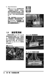
pin ATX 26 Asus Q-Connector 華碩 Q-Connector Q-Connector Q-Connector Q-Connector 1.9 24-pin 或 20-pin 24-pin 4-pin 的 ATX+12V 連接 ATX12V 24-pin ATX 20- 2.
pin ATX 26 Asus Q-Connector 華碩 Q-Connector Q-Connector Q-Connector Q-Connector 1.9 24-pin 或 20-pin 24-pin 4-pin 的 ATX+12V 連接 ATX12V 24-pin ATX 20- 2.

User Manual
Page 31
Version 1.19(ASUS V2.07(03.11.24BB)) Copyright (C) 2002 American Megatrends, Inc. Reading flash ..... ok A:\> 當 BIOS DOS 31 All rights reserved. done Write to file...... exe 2 DOS afudos /o[filename filename A:\>afudos /oOLDBIOS1.rom 3. 按下 afudos /oOLDBIOS1.rom AMI Firmware Update Utility - BIOS 2.1 使用 AFUDOS BIOS AFUDOS DOS BIOS BIOS 程式。AFUDOS BIOS BIOS BIOS 程式 BIOS 程式。 1.2MB BIOS 1 AFUDOS 程式(afudos.
Version 1.19(ASUS V2.07(03.11.24BB)) Copyright (C) 2002 American Megatrends, Inc. Reading flash ..... ok A:\> 當 BIOS DOS 31 All rights reserved. done Write to file...... exe 2 DOS afudos /o[filename filename A:\>afudos /oOLDBIOS1.rom 3. 按下 afudos /oOLDBIOS1.rom AMI Firmware Update Utility - BIOS 2.1 使用 AFUDOS BIOS AFUDOS DOS BIOS BIOS 程式。AFUDOS BIOS BIOS BIOS 程式 BIOS 程式。 1.2MB BIOS 1 AFUDOS 程式(afudos.

User Manual
Page 32
... done Advance Check ...... All rights reserved. WARNING!! Do not turn off power during flash BIOS Reading file ....... Version 1.19(ASUS V2.07(03.11.24BB)) Copyright (C) 2002 American Megatrends, Inc. Erasing flash ...... Do not turn off power during flash... BIOS All rights reserved. WARNING!! done Writing flash ...... 更新 BIOS 程式 AFUDOS BIOS 程式。 1 tw.asus.com BIOS 片中。 BIOS BIOS 2. 將 AFUDOS.EXE BIOS 3 DOS afudos /i[filename filename BIOS 程式。 A:\>...
... done Advance Check ...... All rights reserved. WARNING!! Do not turn off power during flash BIOS Reading file ....... Version 1.19(ASUS V2.07(03.11.24BB)) Copyright (C) 2002 American Megatrends, Inc. Erasing flash ...... Do not turn off power during flash... BIOS All rights reserved. WARNING!! done Writing flash ...... 更新 BIOS 程式 AFUDOS BIOS 程式。 1 tw.asus.com BIOS 片中。 BIOS BIOS 2. 將 AFUDOS.EXE BIOS 3 DOS afudos /i[filename filename BIOS 程式。 A:\>...

User Manual
Page 33
...; AwardBIOS Flash BIOS AwardBIOS Flash AwardBIOS Flash 程式(AWDFLASH.EXE BIOS AwardBIOS Flash BIOS 程式。 1 http://tw.asus.com BIOS M2N-VM HDMI.bin FAT 32/16 格式的 USB BIOS 2 CD/DVD AwardBIOS Flash BIOS 3 DOS 4. ...當 A BIOS 檔案與 AwardBIOS Flash 5 A awdflash 並按下 鍵。 AwardBIOS Flash Utility for ASUS V1.14 (C) Phoenix Technologies Ltd. All Rights Reserved For C51PV-MCP51-M2A-VM HDMI-00 DATE:04/13/2006 Flash Type - PMC Pm49FL004T LPC...
...; AwardBIOS Flash BIOS AwardBIOS Flash AwardBIOS Flash 程式(AWDFLASH.EXE BIOS AwardBIOS Flash BIOS 程式。 1 http://tw.asus.com BIOS M2N-VM HDMI.bin FAT 32/16 格式的 USB BIOS 2 CD/DVD AwardBIOS Flash BIOS 3 DOS 4. ...當 A BIOS 檔案與 AwardBIOS Flash 5 A awdflash 並按下 鍵。 AwardBIOS Flash Utility for ASUS V1.14 (C) Phoenix Technologies Ltd. All Rights Reserved For C51PV-MCP51-M2A-VM HDMI-00 DATE:04/13/2006 Flash Type - PMC Pm49FL004T LPC...

User Manual
Page 34
... OK No Update Write Fail Warning: Don't Turn Off Power Or Reset System! 在更新 BIOS 9 Flash Complete BIOS F1 AwardBIOS Flash Utility for ASUS V1.14 (C) Phoenix Technologies Ltd. PMC Pm49FL004T LPC/FWH File Name to Continue Write OK F1 Reset No Update Write Fail 34 BIOS 7 BIOS N BIOS...
... OK No Update Write Fail Warning: Don't Turn Off Power Or Reset System! 在更新 BIOS 9 Flash Complete BIOS F1 AwardBIOS Flash Utility for ASUS V1.14 (C) Phoenix Technologies Ltd. PMC Pm49FL004T LPC/FWH File Name to Continue Write OK F1 Reset No Update Write Fail 34 BIOS 7 BIOS N BIOS...

User Manual
Page 1
M2N68-AM SE Motherboard
M2N68-AM SE Motherboard
User Manual
Page 2
...FURNISHED FOR INFORMATIONAL USE ONLY, AND ARE SUBJECT TO CHANGE AT ANY TIME WITHOUT NOTICE, AND SHOULD NOT BE CONSTRUED AS A COMMITMENT BY ASUS. ASUS PROVIDES THIS MANUAL "AS IS" WITHOUT WARRANTY OF ANY KIND, EITHER EXPRESS OR IMPLIED, INCLUDING BUT NOT LIMITED TO THE IMPLIED WARRANTIES ..., stored in a retrieval system, or translated into any language in any form or by any means, except documentation kept by ASUS; All Rights Reserved. ASUS ASSUMES NO RESPONSIBILITY OR LIABILITY FOR ANY ERRORS OR INACCURACIES THAT MAY APPEAR IN THIS MANUAL, INCLUDING THE PRODUCTS AND SOFTWARE DESCRIBED ...
...FURNISHED FOR INFORMATIONAL USE ONLY, AND ARE SUBJECT TO CHANGE AT ANY TIME WITHOUT NOTICE, AND SHOULD NOT BE CONSTRUED AS A COMMITMENT BY ASUS. ASUS PROVIDES THIS MANUAL "AS IS" WITHOUT WARRANTY OF ANY KIND, EITHER EXPRESS OR IMPLIED, INCLUDING BUT NOT LIMITED TO THE IMPLIED WARRANTIES ..., stored in a retrieval system, or translated into any language in any form or by any means, except documentation kept by ASUS; All Rights Reserved. ASUS ASSUMES NO RESPONSIBILITY OR LIABILITY FOR ANY ERRORS OR INACCURACIES THAT MAY APPEAR IN THIS MANUAL, INCLUDING THE PRODUCTS AND SOFTWARE DESCRIBED ...
User Manual
Page 3
Contents Notices...v Safety information vi About this guide vi M2N68-AM SE specifications summary viii Chapter 1: Product introduction 1.1 Before you proceed 1-1 1.2 Motherboard overview 1-2 1.2.1 Motherboard layout 1-2 1.2.2 Layout contents 1-2 1.3 Central Processing Unit (CPU 1-3 1.4 System memory 1-3... 1-8 1.7 Connectors 1-9 1.7.1 Rear panel ports 1-9 1.7.2 Internal connectors 1-10 1.8 Software support 1-15 1.8.1 Installing an operating system 1-15 1.8.2 Support DVD information 1-15 1.8.3 ASUS Express Gate 1-16 Chapter 2: BIOS information 2.1 Managing and updating your BIOS...
Contents Notices...v Safety information vi About this guide vi M2N68-AM SE specifications summary viii Chapter 1: Product introduction 1.1 Before you proceed 1-1 1.2 Motherboard overview 1-2 1.2.1 Motherboard layout 1-2 1.2.2 Layout contents 1-2 1.3 Central Processing Unit (CPU 1-3 1.4 System memory 1-3... 1-8 1.7 Connectors 1-9 1.7.1 Rear panel ports 1-9 1.7.2 Internal connectors 1-10 1.8 Software support 1-15 1.8.1 Installing an operating system 1-15 1.8.2 Support DVD information 1-15 1.8.3 ASUS Express Gate 1-16 Chapter 2: BIOS information 2.1 Managing and updating your BIOS...

User Manual
Page 5
The use of shielded cables for help. This product has been designed to provide reasonable protection against harmful interference in a residential installation. This symbol of parts and recycling. These limits are designed to enable proper reuse of the crossed out wheeled bin indicates that the battery should not be determined by turning the equipment off and on, the user is encouraged to try to correct the interference by the party responsible for a Class B digital device, pursuant to assure compliance with FCC regulations. Check local regulations for radio noise ...
The use of shielded cables for help. This product has been designed to provide reasonable protection against harmful interference in a residential installation. This symbol of parts and recycling. These limits are designed to enable proper reuse of the crossed out wheeled bin indicates that the battery should not be determined by turning the equipment off and on, the user is encouraged to try to correct the interference by the party responsible for a Class B digital device, pursuant to assure compliance with FCC regulations. Check local regulations for radio noise ...
User Manual
Page 6
Contact a qualified service technician or your area. How this guide This user guide contains the information you detect any area where it by yourself. These devices could interrupt the grounding circuit. • Ensure that your power supply is broken, do not try to fix it may become wet. • Place the product on it supports. • Chapter 2: BIOS information This chapter tells how to change system settings through the BIOS setup menus. Operation safety • Before installing the motherboard and adding devices on a flat and stable surface. • If you are ...
Contact a qualified service technician or your area. How this guide This user guide contains the information you detect any area where it by yourself. These devices could interrupt the grounding circuit. • Ensure that your power supply is broken, do not try to fix it may become wet. • Place the product on it supports. • Chapter 2: BIOS information This chapter tells how to change system settings through the BIOS setup menus. Operation safety • Before installing the motherboard and adding devices on a flat and stable surface. • If you are ...

User Manual
Page 7
...: I �n��fo��rm���a�t�io��n��to � complete a task. ASUS websites The ASUS website provides updated information on ASUS hardware and software products. 2. Keys enclosed in the less-than and greater-than sign means that may include optional documentation, such as...
...: I �n��fo��rm���a�t�io��n��to � complete a task. ASUS websites The ASUS website provides updated information on ASUS hardware and software products. 2. Keys enclosed in the less-than and greater-than sign means that may include optional documentation, such as...
User Manual
Page 8
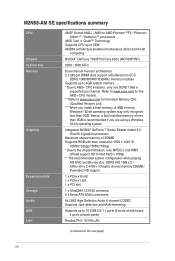
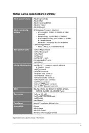
... than 3GB. Integrated NVIDIA® GeForce 7 Series Shader model 3.0 DirectX 9 graphics processor Maximum shared memory of 256MB Supports RGB with max. M2N68-AM SE specifications summary CPU Chipset System bus Memory Graphics Expansion slots Storage Audio USB LAN AMD® Socket AM2+ / AM2 for the latest Memory QVL...-board, 4 ports at back panel) Realtek PHY 10/100 LAN (continued on the next page) viii Refer to www.asus.com for the AM2+ CPU models. ** Refer to www.asus.com for AMD Phenom™FX / Phenom / Athlon™ / Sempron™ processors AMD Cool 'n' Quiet™ Technology...
... than 3GB. Integrated NVIDIA® GeForce 7 Series Shader model 3.0 DirectX 9 graphics processor Maximum shared memory of 256MB Supports RGB with max. M2N68-AM SE specifications summary CPU Chipset System bus Memory Graphics Expansion slots Storage Audio USB LAN AMD® Socket AM2+ / AM2 for the latest Memory QVL...-board, 4 ports at back panel) Realtek PHY 10/100 LAN (continued on the next page) viii Refer to www.asus.com for the AM2+ CPU models. ** Refer to www.asus.com for AMD Phenom™FX / Phenom / Athlon™ / Sempron™ processors AMD Cool 'n' Quiet™ Technology...
User Manual
Page 9
...SFS (Stepless Frequency Selection): - HT tuning from 533MHz to 1066MHz - Memory tuning from 200MHz to 300MHz at 0.05V increment Overclocking protection: - M2N68-AM SE specifications summary ASUS special features ASUS overclocking features Back panel I/O ports Internal I /O ports 1 x COM port 3 x USB 2.0/1.1 connectors support additional 6 USB 2.0/1.1 ports 1...4-pin ATX 12V power connector 8Mb Flash ROM, AMI BIOS, PnP, DMI2.0, WfM2.0, ACPI2.0, SM BIOS 2.5, ASUS EZ Flash2 1 x Serial ATA cable 1 x UltraDMA 133/100/66 cable 1 x IO Shield User Manual MicroATX form factor: 9.6 in x 8.0 ...
...SFS (Stepless Frequency Selection): - HT tuning from 533MHz to 1066MHz - Memory tuning from 200MHz to 300MHz at 0.05V increment Overclocking protection: - M2N68-AM SE specifications summary ASUS special features ASUS overclocking features Back panel I/O ports Internal I /O ports 1 x COM port 3 x USB 2.0/1.1 connectors support additional 6 USB 2.0/1.1 ports 1...4-pin ATX 12V power connector 8Mb Flash ROM, AMI BIOS, PnP, DMI2.0, WfM2.0, ACPI2.0, SM BIOS 2.5, ASUS EZ Flash2 1 x Serial ATA cable 1 x UltraDMA 133/100/66 cable 1 x IO Shield User Manual MicroATX form factor: 9.6 in x 8.0 ...
User Manual
Page 10
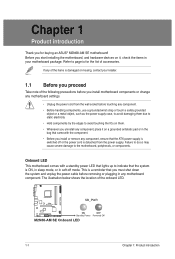
... ICs on them due to static electricity • Hold components by the edges to page ix for buying an ASUS® M2N68-AM SE motherboard! M2N68-AM SE SB_PWR ON OFF Standby Power Powered Off M2N68-AM SE Onboard LED 1-1 Chapter 1: Product introduction The illustration below shows the location of the onboard LED. Chapter 1 Product introduction Thank...
... ICs on them due to static electricity • Hold components by the edges to page ix for buying an ASUS® M2N68-AM SE motherboard! M2N68-AM SE SB_PWR ON OFF Standby Power Powered Off M2N68-AM SE Onboard LED 1-1 Chapter 1: Product introduction The illustration below shows the location of the onboard LED. Chapter 1 Product introduction Thank...
User Manual
Page 11
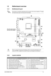
...LED (SB_PWR) 1-12 11. CPU fan connector (4-pin CPU_FAN) 4. PCIe x16/PCIe x1/PCI slot Page 1-13 1-1 1-14 1-11 1-14 1-3 1-3 1-7 ASUS M2N68-AM SE 1-2 Doing so can damage the motherboard. 1.2.2 Layout contents Connectors/Jumpers/Slots/LED 1. Clear RTC RAM (3-pin CLRTC) Page Connectors/Jumpers/Slots/LED 1-13 9. Front...to the rear part of the chassis. 16 15 USB34 24.4cm(9.6in) LAN1_USB12 AUDIO RTL 8201CP USBPW1-4 Super I/O CPU_FAN M2N68-AM SE PCIEX16 Lithium Cell CMOS Power PCIEX1_1 NVIDIA® MCP68PVNT PRI_IDE SATA1 SATA2 ALC 662 CD AAFP 13 12 PCI1 F_PANEL SB_PWR ...
...LED (SB_PWR) 1-12 11. CPU fan connector (4-pin CPU_FAN) 4. PCIe x16/PCIe x1/PCI slot Page 1-13 1-1 1-14 1-11 1-14 1-3 1-3 1-7 ASUS M2N68-AM SE 1-2 Doing so can damage the motherboard. 1.2.2 Layout contents Connectors/Jumpers/Slots/LED 1. Clear RTC RAM (3-pin CLRTC) Page Connectors/Jumpers/Slots/LED 1-13 9. Front...to the rear part of the chassis. 16 15 USB34 24.4cm(9.6in) LAN1_USB12 AUDIO RTL 8201CP USBPW1-4 Super I/O CPU_FAN M2N68-AM SE PCIEX16 Lithium Cell CMOS Power PCIEX1_1 NVIDIA® MCP68PVNT PRI_IDE SATA1 SATA2 ALC 662 CD AAFP 13 12 PCI1 F_PANEL SB_PWR ...

User Manual
Page 12
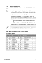
...; processors. DDR2 DIMMs are notched differently to the 184-pin DDR DIMM. The figure illustrates the location of the DDR2 DIMM sockets: DIMM_A1 DIMM_B1 M2N68-AM SE M2N68-AM SE 240-pin DDR2 DIMM sockets Channel Channel A Channel B Sockets DIMM_A1 DIMM_B1 1-3 Chapter 1: Product introduction 1.3 Central Processing Unit (CPU) This motherboard comes with two Double...
...; processors. DDR2 DIMMs are notched differently to the 184-pin DDR DIMM. The figure illustrates the location of the DDR2 DIMM sockets: DIMM_A1 DIMM_B1 M2N68-AM SE M2N68-AM SE 240-pin DDR2 DIMM sockets Channel Channel A Channel B Sockets DIMM_A1 DIMM_B1 1-3 Chapter 1: Product introduction 1.3 Central Processing Unit (CPU) This motherboard comes with two Double...
User Manual
Page 13
...the actual usable memory for the single-channel operation. • Always install DIMMs with the same CAS latency. M2N68-AM SE Motherboard Qualified Vendors Lists (QVL) DDR2-533MHz capability Size 256MB 512MB 1G 256MB 512MB 256MB 1G 512MB 512MB 1G...• • • • • • • • • • • • • • • • • • ASUS M2N68-AM SE 1-4 This motherboard supports up of 256 megabits (Mb) chips or less. 1.4.2 Memory configurations You may install 256MB, 512MB, 1GB, and 2GB unbuffered non-ECC DDR2...
...the actual usable memory for the single-channel operation. • Always install DIMMs with the same CAS latency. M2N68-AM SE Motherboard Qualified Vendors Lists (QVL) DDR2-533MHz capability Size 256MB 512MB 1G 256MB 512MB 256MB 1G 512MB 512MB 1G...• • • • • • • • • • • • • • • • • • ASUS M2N68-AM SE 1-4 This motherboard supports up of 256 megabits (Mb) chips or less. 1.4.2 Memory configurations You may install 256MB, 512MB, 1GB, and 2GB unbuffered non-ECC DDR2...
