
User Guide
Page 6
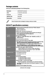
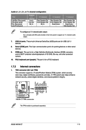
Multi-VGA output support: HDMI, D-SUB ports - H81M-CT specifications summary CPU Chipset Memory Graphics Expansion slots Storage Audio LAN LGA1150 socket for 4th Generation Intel® CoreTM i7/i5/i3, Pentium®... ATA 3.0 Gb/s connector Realtek® ALC887 7.1-channel Audio CODEC - Package contents Check your motherboard package for the following items. Motherboard Cables Accessories Application DVD Documentation ASUS H81M-CT motherboard 2 x Serial ATA 6.0 Gb/s cables 1 x I/O Shield Support DVD User Guide If any of the above items is subject to support an 7.1-channel audio output...
Multi-VGA output support: HDMI, D-SUB ports - H81M-CT specifications summary CPU Chipset Memory Graphics Expansion slots Storage Audio LAN LGA1150 socket for 4th Generation Intel® CoreTM i7/i5/i3, Pentium®... ATA 3.0 Gb/s connector Realtek® ALC887 7.1-channel Audio CODEC - Package contents Check your motherboard package for the following items. Motherboard Cables Accessories Application DVD Documentation ASUS H81M-CT motherboard 2 x Serial ATA 6.0 Gb/s cables 1 x I/O Shield Support DVD User Guide If any of the above items is subject to support an 7.1-channel audio output...

User Guide
Page 9
... object or a metal object, such as indicated in the image. 1.2.2 Screw holes Place six screws into the chassis in the bag that the motherboard fits. ASUS H81M-CT 1-1 Failure to do so may cause severe damage to the motherboard, peripherals, or components. 1.2 Motherboard overview Before you install the motherboard, study the configuration of...
... object or a metal object, such as indicated in the image. 1.2.2 Screw holes Place six screws into the chassis in the bag that the motherboard fits. ASUS H81M-CT 1-1 Failure to do so may cause severe damage to the motherboard, peripherals, or components. 1.2 Motherboard overview Before you install the motherboard, study the configuration of...
User Guide
Page 11
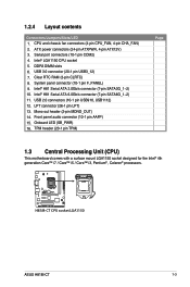
... LED (SB_PWR) 16. 1.2.4 Layout contents Connectors/Jumpers/Slots/LED 1. Intel® H81 Serial ATA 3.0Gb/s connector (7-pin SATA3G_1~2) 10. Intel® LGA1150 CPU socket 5. H81M-CT H81M-CT CPU socket LGA1150 ASUS H81M-CT 1-3 USB 3.0 connector (20-1 pin USB3_12) 7. LPT connector (26-1 pin LPT) 13. TPM header (20-1 pin TPM) Page 1.3 Central Processing Unit (CPU) This motherboard...
... LED (SB_PWR) 16. 1.2.4 Layout contents Connectors/Jumpers/Slots/LED 1. Intel® H81 Serial ATA 3.0Gb/s connector (7-pin SATA3G_1~2) 10. Intel® LGA1150 CPU socket 5. H81M-CT H81M-CT CPU socket LGA1150 ASUS H81M-CT 1-3 USB 3.0 connector (20-1 pin USB3_12) 7. LPT connector (26-1 pin LPT) 13. TPM header (20-1 pin TPM) Page 1.3 Central Processing Unit (CPU) This motherboard...

User Guide
Page 13
ASUS H81M-CT 1-5 4 C 5 A B 1.3.2 CPU heatsink and fan assembly installation Apply the Thermal Interface Material to the CPU heatsink and CPU before you install the heatsink and fan if necessary.
ASUS H81M-CT 1-5 4 C 5 A B 1.3.2 CPU heatsink and fan assembly installation Apply the Thermal Interface Material to the CPU heatsink and CPU before you install the heatsink and fan if necessary.

User Guide
Page 15
... limitation, DDR3 1600MHz and higher memory modules on XMP mode will run at the maximum transfer rate of 512Mb (64MB) chips or less. ASUS H81M-CT 1-7 The system maps the total size of the same version or date code (D/C) from the higher-sized channel is then mapped for the ... the motherboard, the actual usable memory for the OS can be about 3GB or less. DIMM_A1 DIMM_B1 Channel Channel A Channel B Sockets DIMM_A1 DIMM_B1 H81M-CT H81M-CT 240-pin DDR3 DIMM sockets 1.4.2 Memory configurations You may install 1GB, 2GB, 4GB, and 8GB unbuffered non-ECC DDR3 DIMMs into the DIMM sockets...
... limitation, DDR3 1600MHz and higher memory modules on XMP mode will run at the maximum transfer rate of 512Mb (64MB) chips or less. ASUS H81M-CT 1-7 The system maps the total size of the same version or date code (D/C) from the higher-sized channel is then mapped for the ... the motherboard, the actual usable memory for the OS can be about 3GB or less. DIMM_A1 DIMM_B1 Channel Channel A Channel B Sockets DIMM_A1 DIMM_B1 H81M-CT H81M-CT 240-pin DDR3 DIMM sockets 1.4.2 Memory configurations You may install 1GB, 2GB, 4GB, and 8GB unbuffered non-ECC DDR3 DIMMs into the DIMM sockets...
User Guide
Page 17
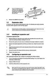
... "Share IRQ" or that came with it by adjusting the software settings. 1. Remove the system unit cover (if your fingers when pressing the retaining clips. ASUS H81M-CT 1-9 Remove the bracket opposite the slot that they support. See Chapter 2 for the expansion card. Support the DIMM lightly with 2 your motherboard is completely seated...
... "Share IRQ" or that came with it by adjusting the software settings. 1. Remove the system unit cover (if your fingers when pressing the retaining clips. ASUS H81M-CT 1-9 Remove the bracket opposite the slot that they support. See Chapter 2 for the expansion card. Support the DIMM lightly with 2 your motherboard is completely seated...
User Guide
Page 19
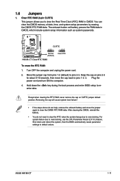
... the system hangs due to clear the Real Time Clock (RTC) RAM in CMOS, which include system setup information such as system passwords. ASUS H81M-CT 1-11 For system failure due to reenter data. Keep the cap on CLRTC jumper default position. Plug the power cord and turn ON the... computer. 4. Hold down and reboot the system, then the BIOS automatically resets parameter settings to pins 2-3. H81M-CT CLRTC 12 23 Normal (Default) H81M-CT Clear RTC RAM Clear RTC To erase the RTC RAM: 1. The onboard button cell battery powers the RAM data in CMOS. ...
... the system hangs due to clear the Real Time Clock (RTC) RAM in CMOS, which include system setup information such as system passwords. ASUS H81M-CT 1-11 For system failure due to reenter data. Keep the cap on CLRTC jumper default position. Plug the power cord and turn ON the... computer. 4. Hold down and reboot the system, then the BIOS automatically resets parameter settings to pins 2-3. H81M-CT CLRTC 12 23 Normal (Default) H81M-CT Clear RTC RAM Clear RTC To erase the RTC RAM: 1. The onboard button cell battery powers the RAM data in CMOS. ...
User Guide
Page 21
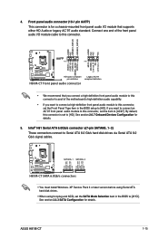
... audio output. 7. LPCPD# GND +3VSB NC LAD0 +3V LAD3 PCIRST# LFRAME# LCLK H81M-CT TPM PIN 1 NC CLKRUN# SERIRQ NC GND LAD1 LAD2 NC GND H81M-CT TPM connector The TPM module is for pointing devices or other protected content. 10. ASUS H81M-CT 1-13 USB 2.0 ports. These 4-pin Universal Serial Bus (USB) ports are for a High...
... audio output. 7. LPCPD# GND +3VSB NC LAD0 +3V LAD3 PCIRST# LFRAME# LCLK H81M-CT TPM PIN 1 NC CLKRUN# SERIRQ NC GND LAD1 LAD2 NC GND H81M-CT TPM connector The TPM module is for pointing devices or other protected content. 10. ASUS H81M-CT 1-13 USB 2.0 ports. These 4-pin Universal Serial Bus (USB) ports are for a High...
User Guide
Page 23
...ASUS H81M-CT 1-15 By default, this connector is for a chassis-mounted front panel audio I /O module cable to this connector. AGND NC SENSE1_RETUR SENSE2_RETUR AGND NC NC NC AAFP PIN 1 PIN 1 MIC2 MICPWR Line out_R NC Line out_L PORT1 L PORT1 R PORT2 R SENSE_SEND PORT2 L H81M-CT HD-audio-compliant pin definition H81M-CT... front panel audio module to this connector to [HD]. H81M-CT SATA6G_1 SATA6G_2 GND RSATA_RXP1 RSATA_RXN1 GND RSATA_TXN1 RSATA_TXP1 GND GND RSATA_RXP2 RSATA_RXN2 GND RSATA_TXN2 RSATA_TXP2 GND H81M-CT SATA 6.0Gb/s connectors • You must install Windows....
...ASUS H81M-CT 1-15 By default, this connector is for a chassis-mounted front panel audio I /O module cable to this connector. AGND NC SENSE1_RETUR SENSE2_RETUR AGND NC NC NC AAFP PIN 1 PIN 1 MIC2 MICPWR Line out_R NC Line out_L PORT1 L PORT1 R PORT2 R SENSE_SEND PORT2 L H81M-CT HD-audio-compliant pin definition H81M-CT... front panel audio module to this connector to [HD]. H81M-CT SATA6G_1 SATA6G_2 GND RSATA_RXP1 RSATA_RXN1 GND RSATA_TXN1 RSATA_TXP1 GND GND RSATA_RXP2 RSATA_RXN2 GND RSATA_TXN2 RSATA_TXP2 GND H81M-CT SATA 6.0Gb/s connectors • You must install Windows....
User Guide
Page 25
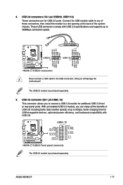
USB+5V USB_P11USB_P11+ GND NC USB+5V USB_P9USB_P9+ GND NC H81M-CT USB910 PIN 1 USB1112 PIN 1 USB+5V USB_P12USB_P12+ GND USB+5V USB_P10USB_P10+ GND H81M-CT USB2.0 connectors Never connect a 1394 cable to a slot opening at the back ...+ GND IntA_P2_SSTXIntA_P2_SSTX+ GND IntA_P2_DIntA_P2_D+ PIN 1 USB3+5V IntA_P1_SSRXIntA_P1_SSRX+ GND IntA_P1_SSTXIntA_P1_SSTX+ GND IntA_P1_DIntA_P1_D+ GND H81M-CT USB3.0 Front panel connector The USB 3.0 module is purchased separately. 9. ASUS H81M-CT 1-17 8. These USB connectors comply with USB 2.0. The USB 2.0 module is purchased separately....
USB+5V USB_P11USB_P11+ GND NC USB+5V USB_P9USB_P9+ GND NC H81M-CT USB910 PIN 1 USB1112 PIN 1 USB+5V USB_P12USB_P12+ GND USB+5V USB_P10USB_P10+ GND H81M-CT USB2.0 connectors Never connect a 1394 cable to a slot opening at the back ...+ GND IntA_P2_SSTXIntA_P2_SSTX+ GND IntA_P2_DIntA_P2_D+ PIN 1 USB3+5V IntA_P1_SSRXIntA_P1_SSRX+ GND IntA_P1_SSTXIntA_P1_SSTX+ GND IntA_P1_DIntA_P1_D+ GND H81M-CT USB3.0 Front panel connector The USB 3.0 module is purchased separately. 9. ASUS H81M-CT 1-17 8. These USB connectors comply with USB 2.0. The USB 2.0 module is purchased separately....

User Guide
Page 27
... any motherboard component. This is a reminder that the system is for the chassis-mounted reset button for the HDD Activity LED. H81M-CT SB_PWR ON OFF Standby Power Powered Off H81M-CT Onboard LED ASUS H81M-CT 1-19 System panel connector (10-1 pin PANEL) This connector supports several chassis-mounted functions. Connect the HDD Activity LED cable...
... any motherboard component. This is a reminder that the system is for the chassis-mounted reset button for the HDD Activity LED. H81M-CT SB_PWR ON OFF Standby Power Powered Off H81M-CT Onboard LED ASUS H81M-CT 1-19 System panel connector (10-1 pin PANEL) This connector supports several chassis-mounted functions. Connect the HDD Activity LED cable...
User Guide
Page 29
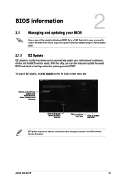
...case you need to restore the BIOS in the future. To launch EZ Update, click EZ Update on the AI Suite 3 main menu bar. ASUS H81M-CT 2-1 BIOS information 2.1 Managing and updating your motherboard's driver, software and firmware Click to find and select the BIOS from file Click to select a...the BIOS EZ Update requires an Internet connection either through a network or an ISP (Internet Service Provider). Copy the original motherboard BIOS using the ASUS Update utility. 2.1.1 EZ Update EZ Update is a utility that allows you can also manually update the saved BIOS and select a boot logo ...
...case you need to restore the BIOS in the future. To launch EZ Update, click EZ Update on the AI Suite 3 main menu bar. ASUS H81M-CT 2-1 BIOS information 2.1 Managing and updating your motherboard's driver, software and firmware Click to find and select the BIOS from file Click to select a...the BIOS EZ Update requires an Internet connection either through a network or an ISP (Internet Service Provider). Copy the original motherboard BIOS using the ASUS Update utility. 2.1.1 EZ Update EZ Update is a utility that allows you can also manually update the saved BIOS and select a boot logo ...
User Guide
Page 31
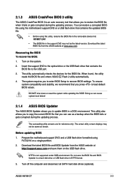
...file. • Before using FAT32/16 on the USB flash drive. Before updating BIOS 1. Do not save them on a single partition. 2. ASUS H81M-CT 2-3 DO NOT shut down or reset the system while updating the BIOS! Prepare the motherboard support DVD and a USB flash drive formatted using ...that you to a hard disk drive or USB flash drive in the support DVD may not be the latest version. 2.1.3 ASUS CrashFree BIOS 3 utility The ASUS CrashFree BIOS 3 is not supported under DOS environment. The utility automatically checks the devices for reference only. Download the latest ...
...file. • Before using FAT32/16 on the USB flash drive. Before updating BIOS 1. Do not save them on a single partition. 2. ASUS H81M-CT 2-3 DO NOT shut down or reset the system while updating the BIOS! Prepare the motherboard support DVD and a USB flash drive formatted using ...that you to a hard disk drive or USB flash drive in the support DVD may not be the latest version. 2.1.3 ASUS CrashFree BIOS 3 utility The ASUS CrashFree BIOS 3 is not supported under DOS environment. The utility automatically checks the devices for reference only. Download the latest ...
User Guide
Page 33
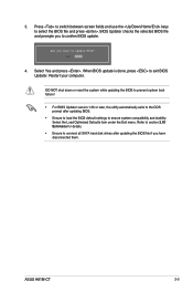
Press to switch between screen fields and use the keys to exit BIOS Updater. Select Yes and press . ASUS H81M-CT 2-5 Restart your computer. When BIOS update is done, press to select the BIOS file and press . Refer to section 2.10 Exit menu for details. • ...
Press to switch between screen fields and use the keys to exit BIOS Updater. Select Yes and press . ASUS H81M-CT 2-5 Restart your computer. When BIOS update is done, press to select the BIOS file and press . Refer to section 2.10 Exit menu for details. • ...
User Guide
Page 35
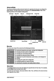
...-up window Last modified settings Navigation keys Quick note Scroll bar Menu bar The menu bar on the menu bar have their respective menu items. ASUS H81M-CT 2-7 Refer to configure the BIOS settings.
...-up window Last modified settings Navigation keys Quick note Scroll bar Menu bar The menu bar on the menu bar have their respective menu items. ASUS H81M-CT 2-7 Refer to configure the BIOS settings.
User Guide
Page 37
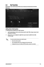
... submenu options • User-configurable items such as language and boot device order • Configuration items such as Memory SPD Information, system time and date ASUS H81M-CT 2-9 Press on your keyboard or right-click on your favorite BIOS items. Adding items to My Favorites To add frequently-used BIOS items to My...
... submenu options • User-configurable items such as language and boot device order • Configuration items such as Memory SPD Information, system time and date ASUS H81M-CT 2-9 Press on your keyboard or right-click on your favorite BIOS items. Adding items to My Favorites To add frequently-used BIOS items to My...
User Guide
Page 39
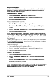
...: 1. After you set a password, this item shows Installed. To change a user password: 1. From the Create New Password box, key in the current password, then press . 3. ASUS H81M-CT 2-11 After you clear the password, the User Password item on top of the screen shows Not Installed. Select the User Password item and press...
...: 1. After you set a password, this item shows Installed. To change a user password: 1. From the Create New Password box, key in the current password, then press . 3. ASUS H81M-CT 2-11 After you clear the password, the User Password item on top of the screen shows Not Installed. Select the User Password item and press...
User Guide
Page 41
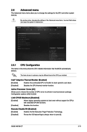
... return to cool down. [Disabled] Disables the CPU thermal monitor function. Be cautious when changing the settings of CPU cores to activate in this function. ASUS H81M-CT 2-13 Active Processor Cores [All] Allows you installed. 2.6 Advanced menu The Advanced menu items allow you to change the settings for CPUs with extended CPUID...
... return to cool down. [Disabled] Disables the CPU thermal monitor function. Be cautious when changing the settings of CPU cores to activate in this function. ASUS H81M-CT 2-13 Active Processor Cores [All] Allows you installed. 2.6 Advanced menu The Advanced menu items allow you to change the settings for CPUs with extended CPUID...
User Guide
Page 43
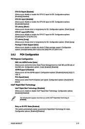
...] [Enabled] [Disabled] ASPM Support [Disabled] Allows you to set the Intel® Rapid Start Technology to Rapid Start Technology S4 mode. Configuration options: [Enabled] [Disabled] ASUS H81M-CT 2-15 Configuration options: [Enabled] [Disabled] CPU C6 report [Enabled] Allows you to disable or enable the CPU C6 report to disable or enable the whole...
...] [Enabled] [Disabled] ASPM Support [Disabled] Allows you to set the Intel® Rapid Start Technology to Rapid Start Technology S4 mode. Configuration options: [Enabled] [Disabled] ASUS H81M-CT 2-15 Configuration options: [Enabled] [Disabled] CPU C6 report [Enabled] Allows you to disable or enable the CPU C6 report to disable or enable the whole...
User Guide
Page 45
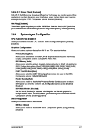
... or disable Intel® Graphics Render Standby support to select the DVMT 5.0 total graphics memory size used by the iGPU. Configuration options: [Auto] [Enabled] [Disabled] ASUS H81M-CT 2-17 Status Check [Enabled] S.M.A.R.T. (Self-Monitoring, Analysis and Reporting Technology) is idle. S.M.A.R.T. When read/write of the iGPU/PCIE Graphics device should be fixed at...
... or disable Intel® Graphics Render Standby support to select the DVMT 5.0 total graphics memory size used by the iGPU. Configuration options: [Auto] [Enabled] [Disabled] ASUS H81M-CT 2-17 Status Check [Enabled] S.M.A.R.T. (Self-Monitoring, Analysis and Reporting Technology) is idle. S.M.A.R.T. When read/write of the iGPU/PCIE Graphics device should be fixed at...


