
User Guide
Page 2
... is eager to Provide Source Code of Certain Software This product contains copyrighted software that we would be extended if: (1) the product is repaired, modified or altered, unless such repair, modification of reproduction and shipment, which you . SPECIFICATIONS AND INFORMATION CONTAINED IN THIS MANUAL ARE FURNISHED FOR INFORMATIONAL USE ONLY, AND ARE SUBJECT TO CHANGE AT ANY TIME WITHOUT...
... is eager to Provide Source Code of Certain Software This product contains copyrighted software that we would be extended if: (1) the product is repaired, modified or altered, unless such repair, modification of reproduction and shipment, which you . SPECIFICATIONS AND INFORMATION CONTAINED IN THIS MANUAL ARE FURNISHED FOR INFORMATIONAL USE ONLY, AND ARE SUBJECT TO CHANGE AT ANY TIME WITHOUT...
User Guide
Page 6
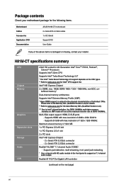
..., front panel jack-restasking * Use a chassis with max.resolution of 1920 x 1200 @60Hz Maximum shared memory of DDR3 1600MHz. H81M-CT specifications summary CPU Chipset Memory Graphics Expansion slots Storage Audio LAN LGA1150 socket for 4th Generation Intel® CoreTM i7/i5/i3, Pentium®, Celeron® Processors Supports Intel® 22nm CPU Supports Intel® Turbo Boost Technology 2.0* * The Intel® Turbo Boost Technology 2.0 support depends on the next page) vi Supports HDMI with max.resolution...
..., front panel jack-restasking * Use a chassis with max.resolution of 1920 x 1200 @60Hz Maximum shared memory of DDR3 1600MHz. H81M-CT specifications summary CPU Chipset Memory Graphics Expansion slots Storage Audio LAN LGA1150 socket for 4th Generation Intel® CoreTM i7/i5/i3, Pentium®, Celeron® Processors Supports Intel® 22nm CPU Supports Intel® Turbo Boost Technology 2.0* * The Intel® Turbo Boost Technology 2.0 support depends on the next page) vi Supports HDMI with max.resolution...
User Guide
Page 7
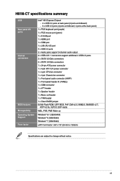
...x Audio jacks support 8-channel audio output 2 x USB 2.0/1.1 connectors support additional 4 USB 2.0 ports 2 x SATA 6.0 Gb/s connectors 2 x SATA 3.0 Gb/s connectors 1 x 24-pin ATX power connector 1 x 4-pin ATX 12V power connector 1 x 4-pin CPU fan connector 1 x 4-pin Chassis fan connector 1 x Front panel audio connector (AAFP) 1 x Front panel header (F_PANEL) 1 x COM connector 1 x LPT header 1 x Speaker header 1 x Mono out header 1 x TPM header 1 x Clear CMOS jumper 64 Mb Flash ROM, UEFI BIOS, PnP, DMI v2.0, WfM2.0, SM BIOS v2.7, ACPI v2.0a, SLP3.0, EUP-ready WOL, PXE, PME Wake up Windows®...
...x Audio jacks support 8-channel audio output 2 x USB 2.0/1.1 connectors support additional 4 USB 2.0 ports 2 x SATA 6.0 Gb/s connectors 2 x SATA 3.0 Gb/s connectors 1 x 24-pin ATX power connector 1 x 4-pin ATX 12V power connector 1 x 4-pin CPU fan connector 1 x 4-pin Chassis fan connector 1 x Front panel audio connector (AAFP) 1 x Front panel header (F_PANEL) 1 x COM connector 1 x LPT header 1 x Speaker header 1 x Mono out header 1 x TPM header 1 x Clear CMOS jumper 64 Mb Flash ROM, UEFI BIOS, PnP, DMI v2.0, WfM2.0, SM BIOS v2.7, ACPI v2.0a, SLP3.0, EUP-ready WOL, PXE, PME Wake up Windows®...

User Guide
Page 15
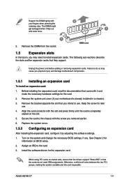
... 512Mb (64MB) chips or less. For effective use of memory, we recommend that you install memory modules of the same version or date code (D/C) from a DDR or DDR2 module. DO NOT install a DDR or DDR2 memory module to the DDR3 slot. For optimal compatibility, we recommend that you do any of the lower-sized channel for single-channel operation. • Due to protect the CPU. ASUS H81M-CT 1-7
... 512Mb (64MB) chips or less. For effective use of memory, we recommend that you install memory modules of the same version or date code (D/C) from a DDR or DDR2 module. DO NOT install a DDR or DDR2 memory module to the DDR3 slot. For optimal compatibility, we recommend that you do any of the lower-sized channel for single-channel operation. • Due to protect the CPU. ASUS H81M-CT 1-7
User Guide
Page 17
... on the system and change the necessary BIOS settings, if any. See Chapter 2 for the card. 2. When using PCI cards on the slot. 5. ASUS H81M-CT 1-9 Remove the DIMM from the socket. Failure to the chassis with the screw you may cause you intend to install expansion cards. Secure the card to do not need to use . 4. Replace the system cover. 1.5.2 Configuring an expansion card After installing the expansion card, configure it flips out 1 with...
... on the system and change the necessary BIOS settings, if any. See Chapter 2 for the card. 2. When using PCI cards on the slot. 5. ASUS H81M-CT 1-9 Remove the DIMM from the socket. Failure to the chassis with the screw you may cause you intend to install expansion cards. Secure the card to do not need to use . 4. Replace the system cover. 1.5.2 Configuring an expansion card After installing the expansion card, configure it flips out 1 with...
User Guide
Page 23
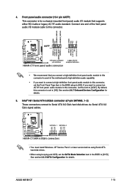
... RSATA_TXP2 GND H81M-CT SATA 6.0Gb/s connectors • You must install Windows. By default, this connector. See section 2.6.7 Onboard Devices Configuration for details. XP Service Pack 3 or later version before using Serial ATA hard disk drives. • When using hot-plug and NCQ, set to [AC97]. Front panel audio connector (10-1 pin AAFP) This connector is for a chassis-mounted front panel audio I /O module cable to this connector is set the SATA Mode Selection item in the BIOS setup to [HD]. 4. Connect one end of the motherboard's high-definition audio capability...
... RSATA_TXP2 GND H81M-CT SATA 6.0Gb/s connectors • You must install Windows. By default, this connector. See section 2.6.7 Onboard Devices Configuration for details. XP Service Pack 3 or later version before using Serial ATA hard disk drives. • When using hot-plug and NCQ, set to [AC97]. Front panel audio connector (10-1 pin AAFP) This connector is for a chassis-mounted front panel audio I /O module cable to this connector is set the SATA Mode Selection item in the BIOS setup to [HD]. 4. Connect one end of the motherboard's high-definition audio capability...
User Guide
Page 24
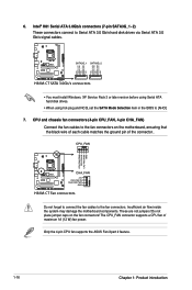
... fan connectors. Do not place jumper caps on the motherboard, ensuring that the black wire of each cable matches the ground pin of maximum 1A (12 W) fan power. Insufficient air flow inside the system may damage the motherboard components. Only the 4-pin CPU fan supports the ASUS Fan Xpert 2 feature. 1-16 Chapter 1: Product introduction XP Service Pack 3 or later version before using Serial ATA hard disk drives. • When using hot-plug and NCQ, set the SATA Mode...
... fan connectors. Do not place jumper caps on the motherboard, ensuring that the black wire of each cable matches the ground pin of maximum 1A (12 W) fan power. Insufficient air flow inside the system may damage the motherboard components. Only the 4-pin CPU fan supports the ASUS Fan Xpert 2 feature. 1-16 Chapter 1: Product introduction XP Service Pack 3 or later version before using Serial ATA hard disk drives. • When using hot-plug and NCQ, set the SATA Mode...
User Guide
Page 25
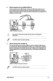
... connectors, then install the module to a slot opening at the back of up to 5Gbps, faster charging time for USB-chargeable devices, optimized power efficiency, and backward compatibility with USB 2.0 specifications and supports up to 480Mbps connection speed. Doing so will damage the motherboard! H81M-CT USB3_12 USB3+5V IntA_P2_SSRXIntA_P2_SSRX+ GND IntA_P2_SSTXIntA_P2_SSTX+ GND IntA_P2_DIntA_P2_D+ PIN 1 USB3+5V IntA_P1_SSRXIntA_P1_SSRX+ GND IntA_P1_SSTXIntA_P1_SSTX+ GND IntA_P1_DIntA_P1_D+ GND H81M-CT USB3.0 Front panel connector The USB...
... connectors, then install the module to a slot opening at the back of up to 5Gbps, faster charging time for USB-chargeable devices, optimized power efficiency, and backward compatibility with USB 2.0 specifications and supports up to 480Mbps connection speed. Doing so will damage the motherboard! H81M-CT USB3_12 USB3+5V IntA_P2_SSRXIntA_P2_SSRX+ GND IntA_P2_SSTXIntA_P2_SSTX+ GND IntA_P2_DIntA_P2_D+ PIN 1 USB3+5V IntA_P1_SSRXIntA_P1_SSRX+ GND IntA_P1_SSTXIntA_P1_SSTX+ GND IntA_P1_DIntA_P1_D+ GND H81M-CT USB3.0 Front panel connector The USB...
User Guide
Page 28
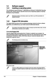
... OS version and corresponding updates to locate the file ASSETUP.EXE from the BIN folder. Click Drivers, Utilities, AHCI Driver, Manual, Contact and Specials tabs to run the Support DVD Place the Support DVD into the optical drive. Refer to your ASUS motherboard. To run the DVD. 1-20 Chapter 1: Product introduction The following screen is for updates. If Autorun is NOT enabled in your computer, the DVD automatically displays the Specials screen which lists...
... OS version and corresponding updates to locate the file ASSETUP.EXE from the BIN folder. Click Drivers, Utilities, AHCI Driver, Manual, Contact and Specials tabs to run the Support DVD Place the Support DVD into the optical drive. Refer to your ASUS motherboard. To run the DVD. 1-20 Chapter 1: Product introduction The following screen is for updates. If Autorun is NOT enabled in your computer, the DVD automatically displays the Specials screen which lists...
User Guide
Page 29
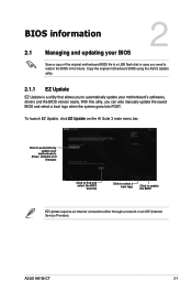
... the BIOS version easily. ASUS H81M-CT 2-1 Copy the original motherboard BIOS using the ASUS Update utility. 2.1.1 EZ Update EZ Update is a utility that allows you to automatically update your motherboard's driver, software and firmware Click to find and select the BIOS from file Click to select a boot logo Click to update the BIOS EZ Update requires an Internet connection either through a network or an ISP (Internet Service Provider). With this utlity, you need to restore the BIOS in case...
... the BIOS version easily. ASUS H81M-CT 2-1 Copy the original motherboard BIOS using the ASUS Update utility. 2.1.1 EZ Update EZ Update is a utility that allows you to automatically update your motherboard's driver, software and firmware Click to find and select the BIOS from file Click to select a boot logo Click to update the BIOS EZ Update requires an Internet connection either through a network or an ISP (Internet Service Provider). With this utlity, you need to restore the BIOS in case...
User Guide
Page 30
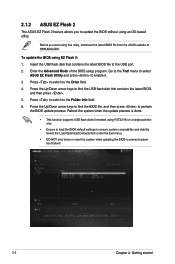
... while updating the BIOS to enable it. 3. 2.1.2 ASUS EZ Flash 2 The ASUS EZ Flash 2 feature allows you start using FAT32/16 on a single partition only. • Ensure to load the BIOS default settings to ensure system compatibility and stability. To update the BIOS using an OS‑based utility. Insert the USB flash disk that contains the latest BIOS, and then press . 5. Enter the Advanced Mode of the BIOS setup program. Press the Up/Down arrow keys...
... while updating the BIOS to enable it. 3. 2.1.2 ASUS EZ Flash 2 The ASUS EZ Flash 2 feature allows you start using FAT32/16 on a single partition only. • Ensure to load the BIOS default settings to ensure system compatibility and stability. To update the BIOS using an OS‑based utility. Insert the USB flash disk that contains the latest BIOS, and then press . 5. Enter the Advanced Mode of the BIOS setup program. Press the Up/Down arrow keys...
User Guide
Page 31
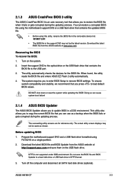
... save the BIOS file and BIOS Updater to load default BIOS values. The succeeding utility screens are for the BIOS file. DO NOT shut down or reset the system while updating the BIOS! 2.1.3 ASUS CrashFree BIOS 3 utility The ASUS CrashFree BIOS 3 is not supported under DOS environment. You can restore a corrupted BIOS file using the motherboard support DVD or a USB flash drive that you to enter BIOS Setup to the USB port. 3. Turn on the USB flash drive. The system requires you press to a hard disk drive or USB flash drive in the support DVD may...
... save the BIOS file and BIOS Updater to load default BIOS values. The succeeding utility screens are for the BIOS file. DO NOT shut down or reset the system while updating the BIOS! 2.1.3 ASUS CrashFree BIOS 3 utility The ASUS CrashFree BIOS 3 is not supported under DOS environment. You can restore a corrupted BIOS file using the motherboard support DVD or a USB flash drive that you to enter BIOS Setup to the USB port. 3. Turn on the USB flash drive. The system requires you press to a hard disk drive or USB flash drive in the support DVD may...
User Guide
Page 33
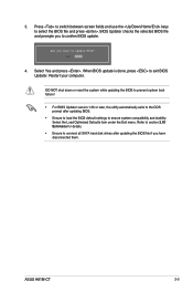
... BIOS to prevent system boot failure! • For BIOS Updater version 1.30 or later, the utility automatically exits to the DOS prompt after updating the BIOS file if you to select the BIOS file and press . Press to switch between screen fields and use the keys to confirm BIOS update. 4. Refer to section 2.10 Exit menu for details. • Ensure to connect all SATA hard disk drives after updating BIOS. • Ensure to load the BIOS default settings to exit BIOS Updater...
... BIOS to prevent system boot failure! • For BIOS Updater version 1.30 or later, the utility automatically exits to the DOS prompt after updating the BIOS file if you to select the BIOS file and press . Press to switch between screen fields and use the keys to confirm BIOS update. 4. Refer to section 2.10 Exit menu for details. • Ensure to connect all SATA hard disk drives after updating BIOS. • Ensure to load the BIOS default settings to exit BIOS Updater...

User Guide
Page 42
...[Disabled] Disables the CPU C states. Boot performance mode [Max Non-Tu...] This item allows you to enable or disable the Enhanced Intel® SpeedStep Technology (EIST). [Disabled] The CPU runs at its default speed. [Enabled] The operating system controls the CPU speed. EIST [Enabled] Allows you to select the boot performance mode. Configuration options: [Enabled] [Disabled] Turbo Mode is only available on selected CPU models only. Intel Virtualization Technology [Disabled] [Enabled] Allows a hardware platform to run faster than the marked frequency in a specific...
...[Disabled] Disables the CPU C states. Boot performance mode [Max Non-Tu...] This item allows you to enable or disable the Enhanced Intel® SpeedStep Technology (EIST). [Disabled] The CPU runs at its default speed. [Enabled] The operating system controls the CPU speed. EIST [Enabled] Allows you to select the boot performance mode. Configuration options: [Enabled] [Disabled] Turbo Mode is only available on selected CPU models only. Intel Virtualization Technology [Disabled] [Enabled] Allows a hardware platform to run faster than the marked frequency in a specific...
User Guide
Page 43
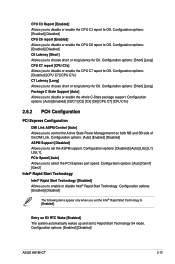
...set to Rapid Start Technology S4 mode. Configuration options: [Short] [Long] Package C State Support [Auto] Allows you to select the PCI Express port speed. PCIe Speed [Auto] Allows you to disable or enable the whole C-State package support. Entry on both NB and SB side of the DMI Link. Configuration options: [Enabled] [Disabled] ASUS H81M-CT 2-15 Configuration options: [Auto] [Enabled] [C0/C1] [C2] [C3] [C6] [CPU C7] [CPU C7s] 2.6.2 PCH Configuration PCI Express Configuration DMI Link ASPM Control [Auto] Allows you to set the ASPM support. Configuration options: [Auto] [Enabled...
...set to Rapid Start Technology S4 mode. Configuration options: [Short] [Long] Package C State Support [Auto] Allows you to select the PCI Express port speed. PCIe Speed [Auto] Allows you to disable or enable the whole C-State package support. Entry on both NB and SB side of the DMI Link. Configuration options: [Enabled] [Disabled] ASUS H81M-CT 2-15 Configuration options: [Auto] [Enabled] [C0/C1] [C2] [C3] [C6] [CPU C7] [CPU C7s] 2.6.2 PCH Configuration PCI Express Configuration DMI Link ASPM Control [Auto] Allows you to set the ASPM support. Configuration options: [Auto] [Enabled...
User Guide
Page 44
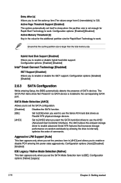
... Connect Technology [Disabled] ISCT Support [Disabled] Allows you to enable or disable PCH entering link power state aggressively. Configuration options: [Enabled] [Disabled] 2.6.3 SATA Configuration While entering Setup, the BIOS automatically detects the presence of commands. The SATA Port items show Not Present if no SATA device is installed to internally optimize the order of SATA devices. The AHCI allows the onboard storage driver to enable advanced Serial ATA features that the caching partition size is not enough for Rapid Start Technology to enable or disable hybrid hard disk...
... Connect Technology [Disabled] ISCT Support [Disabled] Allows you to enable or disable PCH entering link power state aggressively. Configuration options: [Enabled] [Disabled] 2.6.3 SATA Configuration While entering Setup, the BIOS automatically detects the presence of commands. The SATA Port items show Not Present if no SATA device is installed to internally optimize the order of SATA devices. The AHCI allows the onboard storage driver to enable advanced Serial ATA features that the caching partition size is not enough for Rapid Start Technology to enable or disable hybrid hard disk...
User Guide
Page 45
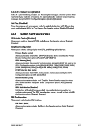
... [Auto] [Disabled] [Enabled] iGPU Multi-Monitor [Disabled] Set this feature allows the hard disk to select a primary display from iGPU, and PCIe graphical devices. Configuration options: [Auto] [iGPU] [PCIE] [PCI] iGPU Memory [Auto] Allows you to report warning messages during the POST. The iGPU shared system memory size will be the Primary Display. DMI Gen 2 [Auto] Allows you to enable or disable DMI Gen 2. Configuration options: [Auto] [Enabled] [Disabled] ASUS H81M-CT 2-17 S.M.A.R.T. Status Check [Enabled] S.M.A.R.T. (Self-Monitoring, Analysis and Reporting Technology...
... [Auto] [Disabled] [Enabled] iGPU Multi-Monitor [Disabled] Set this feature allows the hard disk to select a primary display from iGPU, and PCIe graphical devices. Configuration options: [Auto] [iGPU] [PCIE] [PCI] iGPU Memory [Auto] Allows you to report warning messages during the POST. The iGPU shared system memory size will be the Primary Display. DMI Gen 2 [Auto] Allows you to enable or disable DMI Gen 2. Configuration options: [Auto] [Enabled] [Disabled] ASUS H81M-CT 2-17 S.M.A.R.T. Status Check [Enabled] S.M.A.R.T. (Self-Monitoring, Analysis and Reporting Technology...

User Guide
Page 46
.... 2.6.5 USB Configuration The items in OS during bootup. [Enabled] Enables the function. [Disabled] Disables the function. 2-18 Chapter 2: Getting started Memory Remap [Enabled] Allows you to enable or disable remapping the memory above 4GB. [Enabled] Enables the function. [Disabled] Disables this menu allow you to enable or disable the control of Active State Power Management on legacy operating systems (OS). [Auto] Allows the system to configure the NB PCI Express settings. Intel xHCI Mode [Smart Auto] [Smart Auto] Enables the operation of xHCI controller. [Auto...
.... 2.6.5 USB Configuration The items in OS during bootup. [Enabled] Enables the function. [Disabled] Disables the function. 2-18 Chapter 2: Getting started Memory Remap [Enabled] Allows you to enable or disable remapping the memory above 4GB. [Enabled] Enables the function. [Disabled] Disables this menu allow you to enable or disable the control of Active State Power Management on legacy operating systems (OS). [Auto] Allows the system to configure the NB PCI Express settings. Intel xHCI Mode [Smart Auto] [Smart Auto] Enables the operation of xHCI controller. [Auto...

User Guide
Page 48
... serial port configuration. Change Settings [Auto] Allows you to enable or disable the PXE OptionRom of the Realtek LAN controller. Realtek PXE Option Rom [Disabled] This item appears only when you set the previous item to [Enabled] and allows you to select an optimal setting for Super I/O devices. Configuration options: [Enabled] [Disabled] Serial Port / Serial Port 1 Configuration The sub-items in this menu allow you set the Parallel Port Configuration item to [Enabled]. IRQ=5,6,7,9,10,11,12;] [IO=278h; Configuration options: [STD Printer Mode...
... serial port configuration. Change Settings [Auto] Allows you to enable or disable the PXE OptionRom of the Realtek LAN controller. Realtek PXE Option Rom [Disabled] This item appears only when you set the previous item to [Enabled] and allows you to select an optimal setting for Super I/O devices. Configuration options: [Enabled] [Disabled] Serial Port / Serial Port 1 Configuration The sub-items in this menu allow you set the Parallel Port Configuration item to [Enabled]. IRQ=5,6,7,9,10,11,12;] [IO=278h; Configuration options: [STD Printer Mode...
User Guide
Page 49
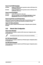
...PCIE/PCI devices to disable or enable the UEFI network stack. Configuration options: [S1 only (CPU Stop Clock)] [S3 only (Suspend to RAM)] Support G3 Wakeup [Disabled] Allows you set values. Configuration options: [Enabled] [Disabled] 2.6.9 Network Stack Configuration Network Stack [Disabled] This item allows user to generate a wake-on-LAN feature of the Intel®/Realtek LAN device. Configuration options: [Disabled] [Enabled] Ipv6 PXE Support [Enabled] This item allows user to disable or enable the Ipv4 PXE Boot support. Power On By RTC [S1 only (CPU Stop Clock)] Select the ACPI...
...PCIE/PCI devices to disable or enable the UEFI network stack. Configuration options: [S1 only (CPU Stop Clock)] [S3 only (Suspend to RAM)] Support G3 Wakeup [Disabled] Allows you set values. Configuration options: [Enabled] [Disabled] 2.6.9 Network Stack Configuration Network Stack [Disabled] This item allows user to generate a wake-on-LAN feature of the Intel®/Realtek LAN device. Configuration options: [Disabled] [Enabled] Ipv6 PXE Support [Enabled] This item allows user to disable or enable the Ipv4 PXE Boot support. Power On By RTC [S1 only (CPU Stop Clock)] Select the ACPI...


