TravelMate 6593 Service Guide
Page 7
...Acer GridVista (dual-display compatible 27 Hardware Specifications and Configurations 29 System Utilities 37 BIOS Setup Utility 37 Navigating the BIOS Utility 38 Information 39 Main 40 Security 42 Boot 46 Exit 47 BIOS Flash Utility 48 Remove HDD/BIOS Utility 49 Machine Disassembly and Replacement 53 Disassembly... Requirements 53 General Information 54 Pre-disassembly Instructions 54 Disassembly Process 54 External Module Disassembly Process 55 External Modules Disassembly Flowchart 55 Removing the ...
...Acer GridVista (dual-display compatible 27 Hardware Specifications and Configurations 29 System Utilities 37 BIOS Setup Utility 37 Navigating the BIOS Utility 38 Information 39 Main 40 Security 42 Boot 46 Exit 47 BIOS Flash Utility 48 Remove HDD/BIOS Utility 49 Machine Disassembly and Replacement 53 Disassembly... Requirements 53 General Information 54 Pre-disassembly Instructions 54 Disassembly Process 54 External Module Disassembly Process 55 External Modules Disassembly Flowchart 55 Removing the ...
TravelMate 6593 Service Guide
Page 8
... 86 Removing the Main Board 90 Removing the Daughter Board Module 94 Removing the Speaker Module 95 LCD Module Disassembly Process 97 LCD Module Disassembly Flowchart 97 Removing the LCD Bezel 98 Removing the LCD Panel with the Brackets 100 Removing the Inverter Board... 128 Clearing Password Check 128 BIOS Recovery by Crisis Disk 129 FRU (Field Replaceable Unit) List 131 TravelMate 6593 Series Exploded Diagram 132 Model Definition and Configuration 140 TravelMate 6593 Series 140 Test Compatible Components 163 Microsoft® Windows® Vista Environment Test 164 VIII
... 86 Removing the Main Board 90 Removing the Daughter Board Module 94 Removing the Speaker Module 95 LCD Module Disassembly Process 97 LCD Module Disassembly Flowchart 97 Removing the LCD Bezel 98 Removing the LCD Panel with the Brackets 100 Removing the Inverter Board... 128 Clearing Password Check 128 BIOS Recovery by Crisis Disk 129 FRU (Field Replaceable Unit) List 131 TravelMate 6593 Series Exploded Diagram 132 Model Definition and Configuration 140 TravelMate 6593 Series 140 Test Compatible Components 163 Microsoft® Windows® Vista Environment Test 164 VIII
TravelMate 6593 Service Guide
Page 63
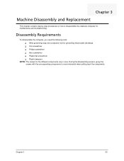
... Replacement This chapter contains step-by-step procedures on how to avoid mismatch when putting back the components. Disassembly Requirements To disassemble the computer, you need the following tools: K Wrist grounding strap and conductive mat for preventing electrostatic discharge K Flat screwdriver K Philips screwdriver K Hex screwdriver K Plastic flat ...
... Replacement This chapter contains step-by-step procedures on how to avoid mismatch when putting back the components. Disassembly Requirements To disassemble the computer, you need the following tools: K Wrist grounding strap and conductive mat for preventing electrostatic discharge K Flat screwdriver K Philips screwdriver K Hex screwdriver K Plastic flat ...

TravelMate 6593 Service Guide
Page 64
...Remove the battery pack. Observe the order of the hardware components. Unplug the AC adapter and all peripherals. 2. Disassembly Process The disassembly process is divided into the following : 1. Turn off the power to the system and all power and signal...main board, you do the following stages: • External module disassembly • Main unit disassembly • LCD module disassembly The flowcharts provided in that order. General Information Pre-disassembly Instructions Before proceeding with the disassembly procedure, make sure that you must first remove the keyboard, ...
...Remove the battery pack. Observe the order of the hardware components. Unplug the AC adapter and all peripherals. 2. Disassembly Process The disassembly process is divided into the following : 1. Turn off the power to the system and all power and signal...main board, you do the following stages: • External module disassembly • Main unit disassembly • LCD module disassembly The flowcharts provided in that order. General Information Pre-disassembly Instructions Before proceeding with the disassembly procedure, make sure that you must first remove the keyboard, ...
TravelMate 6593 Service Guide
Page 65
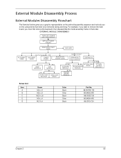
... The flowchart below gives you a graphic representation on the entire disassembly sequence and instructs you must first remove the keyboard, then disassemble the inside assembly frame in that need to be removed during servicing. EXTERNAL MODULE DISASSEMBLY TURN OFF POWER AND PERIPHERALS UNPLUG POWER CABLES REMOVE BATTERY PACK SIM CARD PC DUMMY CARD...
... The flowchart below gives you a graphic representation on the entire disassembly sequence and instructs you must first remove the keyboard, then disassemble the inside assembly frame in that need to be removed during servicing. EXTERNAL MODULE DISASSEMBLY TURN OFF POWER AND PERIPHERALS UNPLUG POWER CABLES REMOVE BATTERY PACK SIM CARD PC DUMMY CARD...
TravelMate 6593 Service Guide
Page 81
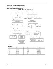
Main Unit Disassembly Process Main Unit Disassembly Flowchart MAIN UNIT DISASSEMBLY MAIN UNIT MIDDLE COVER Ax 2 KEYBOARD B x 2 HEAT SINK FAN SCREW X 4 (CPU) SCREW X 2 (VGA) CPU/VGA THERMAL MODULE Cx4 LCD MODULE C x 9 UPPER CASE Ax 1 DAUGHTER BOARD ...
Main Unit Disassembly Process Main Unit Disassembly Flowchart MAIN UNIT DISASSEMBLY MAIN UNIT MIDDLE COVER Ax 2 KEYBOARD B x 2 HEAT SINK FAN SCREW X 4 (CPU) SCREW X 2 (VGA) CPU/VGA THERMAL MODULE Cx4 LCD MODULE C x 9 UPPER CASE Ax 1 DAUGHTER BOARD ...
TravelMate 6593 Service Guide
Page 179
... 29 D DIMM Module 62 Display 3 display hotkeys 16 E Error Symptom-to-Spare Part Index 112 Euro 17 External CD-ROM Drive Check 108 External Module Disassembly Flowchart 55 F Index Features 1 Fingerprint Board 86 Flash Utility 48 fpc cable 101 FRU (Field Replaceable Unit) List 131 H Hard disk 31 Hard Disk Drive... 127 Top View 127 K Keyboard 33, 73 Keyboard or Auxiliary Input Device Check 108 L Launch Board 84 LCD Bezel 98 LCD Brackets 105 LCD Module Disassembly Flowchart 97 LCD with the Brackets 100 lower cover 60 M Main Unit...
... 29 D DIMM Module 62 Display 3 display hotkeys 16 E Error Symptom-to-Spare Part Index 112 Euro 17 External CD-ROM Drive Check 108 External Module Disassembly Flowchart 55 F Index Features 1 Fingerprint Board 86 Flash Utility 48 fpc cable 101 FRU (Field Replaceable Unit) List 131 H Hard disk 31 Hard Disk Drive... 127 Top View 127 K Keyboard 33, 73 Keyboard or Auxiliary Input Device Check 108 L Launch Board 84 LCD Bezel 98 LCD Brackets 105 LCD Module Disassembly Flowchart 97 LCD with the Brackets 100 lower cover 60 M Main Unit...


