Acer Aspire X3475 Desktop Service Guide
Page 7
... Assembly 27 Disassembly Requirements 27 Pre-disassembly Procedure 28 Removing the Side Panel 29 Removing the Front Bezel 30 Removing the Heat Sink Fan Assembly 31 Removing the Processor 34 Removing the HDD-ODD Bracket 36 Removing the Optical Drive and the Hard Disk Drive 37 Detaching the Front Bezel 41 Removing the Wireless Lan Card 42 Removing the VGA Card 43 Removing the Memory Modules 44 Removing the Power Supply 45 Removing the Mainboard 47 Removing the USB, Audio and Card Reader Boards 50 Assembly...
... Assembly 27 Disassembly Requirements 27 Pre-disassembly Procedure 28 Removing the Side Panel 29 Removing the Front Bezel 30 Removing the Heat Sink Fan Assembly 31 Removing the Processor 34 Removing the HDD-ODD Bracket 36 Removing the Optical Drive and the Hard Disk Drive 37 Detaching the Front Bezel 41 Removing the Wireless Lan Card 42 Removing the VGA Card 43 Removing the Memory Modules 44 Removing the Power Supply 45 Removing the Mainboard 47 Removing the USB, Audio and Card Reader Boards 50 Assembly...
Acer Aspire X3475 Desktop Service Guide
Page 8
... Fan Assembly 76 Reinstalling the Front Bezel 78 Reinstalling the Side Panel 79 System Troubleshooting 80 Hardware Diagnostic Procedure 80 System Check Procedures 81 Power System Check 81 System External Inspection 81 System Internal Inspection 81 Beep Codes 82 Checkpoints 83 BIOS Recovery 86 Jumper and Connector Information 87 M/B Placement 87 Jumper Setting 89 Internal Header Pin Definition 90 Connector Pin Definition 93 FRU (Field Replaceable Unit) List 96 Aspire X3475 Exploded Diagram 97 Aspire X3475 FRU List...
... Fan Assembly 76 Reinstalling the Front Bezel 78 Reinstalling the Side Panel 79 System Troubleshooting 80 Hardware Diagnostic Procedure 80 System Check Procedures 81 Power System Check 81 System External Inspection 81 System Internal Inspection 81 Beep Codes 82 Checkpoints 83 BIOS Recovery 86 Jumper and Connector Information 87 M/B Placement 87 Jumper Setting 89 Internal Header Pin Definition 90 Connector Pin Definition 93 FRU (Field Replaceable Unit) List 96 Aspire X3475 Exploded Diagram 97 Aspire X3475 FRU List...
Acer Aspire X3475 Desktop Service Guide
Page 10
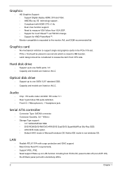
...-in second slot which is requested to release the latch from S3,S4,S5, power button off (non-ACPI OS). Serial ATA controller • Connector Type: SATAIII connector. • Connector Quantity: 3(3 * 6Gb/s) • Storage Type support: • 3.5" SATAII/SATAIII HDD. • DVD-ROM/DVD-RW/DVD+RW/DVD Dual/DVD SuperMultiPlus/ Blu-Ray ODD. • AHCI/IDE mode option • Default AHCI mode in non-windows OS. Graphics • HD Graphics Support: • Support Digital display HDMI, DVI and VGA. •...
...-in second slot which is requested to release the latch from S3,S4,S5, power button off (non-ACPI OS). Serial ATA controller • Connector Type: SATAIII connector. • Connector Quantity: 3(3 * 6Gb/s) • Storage Type support: • 3.5" SATAII/SATAIII HDD. • DVD-ROM/DVD-RW/DVD+RW/DVD Dual/DVD SuperMultiPlus/ Blu-Ray ODD. • AHCI/IDE mode option • Default AHCI mode in non-windows OS. Graphics • HD Graphics Support: • Support Digital display HDMI, DVI and VGA. •...
Acer Aspire X3475 Desktop Service Guide
Page 11
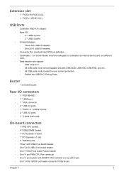
... CPU Fan connector • One* 4 pin System with SAMRT FAN controller (co-lay with 3 pin) • One* H1X4 SPDIF out header closed to cardreader as internal device and use different color. • Data transfer rate support: • USB 3.0/2.0/1.1 • All USB ports must be boot-capable includes USB-ODD, USB-HDD, USB-FDD, and etc... • All USB ports must provide the over current protection. • Enable the USB EHCI Debug Ports. Rear I /O: • 4 * USB2.0 ports...
... CPU Fan connector • One* 4 pin System with SAMRT FAN controller (co-lay with 3 pin) • One* H1X4 SPDIF out header closed to cardreader as internal device and use different color. • Data transfer rate support: • USB 3.0/2.0/1.1 • All USB ports must be boot-capable includes USB-ODD, USB-HDD, USB-FDD, and etc... • All USB ports must provide the over current protection. • Enable the USB EHCI Debug Ports. Rear I /O: • 4 * USB2.0 ports...
Acer Aspire X3475 Desktop Service Guide
Page 12
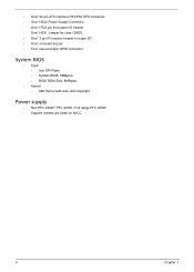
... Power Supply Connector • One* H7x2 pin front panel IO header • One* H3X1 Jumper for clear CMOS • One* 3 pin IR receiver header to super I/O • One* on AVLC. 4 Chapter 1 Power supply • Non PFC 220W / PFC 220W / Full range PFC 220W. • Support models are listed on board buzzer • Two* reserved 2pin GPIO connector System BIOS • Type: • Use SPI Flash. • System BIOS: 8MBytes. • BIOS ROM Size...
... Power Supply Connector • One* H7x2 pin front panel IO header • One* H3X1 Jumper for clear CMOS • One* 3 pin IR receiver header to super I/O • One* on AVLC. 4 Chapter 1 Power supply • Non PFC 220W / PFC 220W / Full range PFC 220W. • Support models are listed on board buzzer • Two* reserved 2pin GPIO connector System BIOS • Type: • Use SPI Flash. • System BIOS: 8MBytes. • BIOS ROM Size...
Acer Aspire X3475 Desktop Service Guide
Page 16
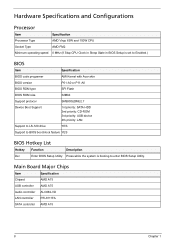
... A75 USB controller AMD A75 Audio controller ALC662-VD LAN controller RTL8111FA SATA controller AMD A75 8 Chapter 1 Hardware Specifications and Configurations Processor Item Specification Processor Type AMD Virgo 65W and 100W CPU Socket Type AMD FM2 Minimum operating speed 0 MHz (If Stop CPU Clock in Sleep State in BIOS Setup is set to Enabled.) BIOS Item Specification BIOS code programer AMI Kernel with Acer skin BIOS version P01-A0 or P11-A0 BIOS ROM type SPI Flash BIOS ROM size 32Mbit Support protocol SMBIOS(DMI)2.7 Device Boot Support 1st priority: SATA HDD...
... A75 USB controller AMD A75 Audio controller ALC662-VD LAN controller RTL8111FA SATA controller AMD A75 8 Chapter 1 Hardware Specifications and Configurations Processor Item Specification Processor Type AMD Virgo 65W and 100W CPU Socket Type AMD FM2 Minimum operating speed 0 MHz (If Stop CPU Clock in Sleep State in BIOS Setup is set to Enabled.) BIOS Item Specification BIOS code programer AMI Kernel with Acer skin BIOS version P01-A0 or P11-A0 BIOS ROM type SPI Flash BIOS ROM size 32Mbit Support protocol SMBIOS(DMI)2.7 Device Boot Support 1st priority: SATA HDD...
Acer Aspire X3475 Desktop Service Guide
Page 17
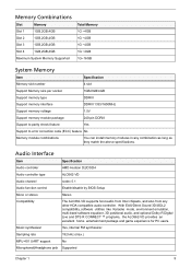
... Supported Chapter 1 9 Music synthesizer Yes, internal FM synthesizer. With EAX/Direct Sound 3D/I3DL2 compatibility, software utilities like Karaoke mode, environment emulation, multi-band software equalizer, 3D positional audio, and optional Dolby R Digital Live and DTS R CONNECT ™ programs, the ALC662-VD provides an excellent home entertainment package and game experience for PC users. Memory Combinations Slot Memory Slot 1 1GB,2GB,4GB Slot 2 1GB,2GB,4GB Slot...
... Supported Chapter 1 9 Music synthesizer Yes, internal FM synthesizer. With EAX/Direct Sound 3D/I3DL2 compatibility, software utilities like Karaoke mode, environment emulation, multi-band software equalizer, 3D positional audio, and optional Dolby R Digital Live and DTS R CONNECT ™ programs, the ALC662-VD provides an excellent home entertainment package and game experience for PC users. Memory Combinations Slot Memory Slot 1 1GB,2GB,4GB Slot 2 1GB,2GB,4GB Slot...
Acer Aspire X3475 Desktop Service Guide
Page 19
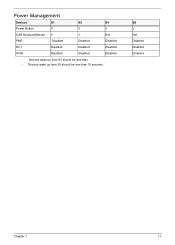
S5 V N/A Disabled Disabled Disabled Chapter 1 11 Power Management Devices S1 S3 S4 Power Button V V V USB Keyboard/Mouse V V N/A PME Disabled Disabled Disabled RCT Disabled Disabled Disabled WOR Disabled Disabled Disabled • Devices wake up from S3 should be less than. • Devices wake up from S5 should be less than 10 seconds.
S5 V N/A Disabled Disabled Disabled Chapter 1 11 Power Management Devices S1 S3 S4 Power Button V V V USB Keyboard/Mouse V V N/A PME Disabled Disabled Disabled RCT Disabled Disabled Disabled WOR Disabled Disabled Disabled • Devices wake up from S3 should be less than. • Devices wake up from S5 should be less than 10 seconds.
Acer Aspire X3475 Desktop Service Guide
Page 20
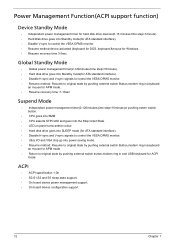
... in,keyboard an mouse for APM mode. • Resume recovery time :7-10sec Suspend Mode • Independent power management timer(2-120minutes,time step=10minute)or pushing extern switch button. • CPU goes into SMM • CPU asserts STPCLK# and goes into the Stop Grant State. • LED on panel turns amber colour. • Hard disk drive goes into SLEEP mode (for ATA standard interface). • Disable H-sync and V-sync signals to control the...
... in,keyboard an mouse for APM mode. • Resume recovery time :7-10sec Suspend Mode • Independent power management timer(2-120minutes,time step=10minute)or pushing extern switch button. • CPU goes into SMM • CPU asserts STPCLK# and goes into the Stop Grant State. • LED on panel turns amber colour. • Hard disk drive goes into SLEEP mode (for ATA standard interface). • Disable H-sync and V-sync signals to control the...
Acer Aspire X3475 Desktop Service Guide
Page 21
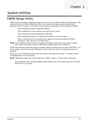
... power management configuration • When changing the password or making other changes to the security setup • When a configuration error is not part of the system RAM which allows configuration data to run this guide. The system reboots immediately after you have saved all open files. NOTE: CMOS Setup Utility will need to be bad. Chapter 2 13 These values may be retained when power is turned off. In this case, the system cannot retain configuration...
... power management configuration • When changing the password or making other changes to the security setup • When a configuration error is not part of the system RAM which allows configuration data to run this guide. The system reboots immediately after you have saved all open files. NOTE: CMOS Setup Utility will need to be bad. Chapter 2 13 These values may be retained when power is turned off. In this case, the system cannot retain configuration...
Acer Aspire X3475 Desktop Service Guide
Page 23
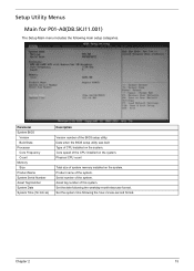
.... Set the system time following the weekday-month-day-year format. Chapter 2 15 Asset tag number of the system. Date when the BIOS setup utility was built Type of system memory installed on the system. Setup Utility Menus Main for P01-A0(DB.SKJ11.001) The Setup Main menu includes the following main setup categories. Parameter System BIOS Version Build Date Processor Core Frequency Count Memory...
.... Set the system time following the weekday-month-day-year format. Chapter 2 15 Asset tag number of the system. Date when the BIOS setup utility was built Type of system memory installed on the system. Setup Utility Menus Main for P01-A0(DB.SKJ11.001) The Setup Main menu includes the following main setup categories. Parameter System BIOS Version Build Date Processor Core Frequency Count Memory...
Acer Aspire X3475 Desktop Service Guide
Page 24
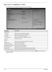
.... Product name of this system. Serial number of the CPU installed on the system. Date when the BIOS setup utility was built Type of the system. Core speed of the motherboard. Set the system time following the weekday-month-day-year format. Serial number of CPU installed on the system. Main for P11-A0(DB.SLV11.001) The Setup Main menu includes the following each of the BIOS setup utility.
.... Product name of this system. Serial number of the CPU installed on the system. Date when the BIOS setup utility was built Type of the system. Core speed of the motherboard. Set the system time following the weekday-month-day-year format. Serial number of CPU installed on the system. Main for P11-A0(DB.SLV11.001) The Setup Main menu includes the following each of the BIOS setup utility.
Acer Aspire X3475 Desktop Service Guide
Page 27
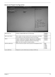
... the OS to change the setting. Displays the current unified memory architecture (UMA) size. Advanced Chipset Configuration AMD Turbo Core AMD Cooler'n'Quiet AMD-V UMA Free Buffer Size Current UMA Size Enables or disables AMD Turbo Core Technology. If enabled, a virtual machine manager (VMM) can utilize the additional hardware virtualization capabilities provided by the Intel graphics device. When disabled, the system operates at maximum CPU speed. When enabled, this technology.
... the OS to change the setting. Displays the current unified memory architecture (UMA) size. Advanced Chipset Configuration AMD Turbo Core AMD Cooler'n'Quiet AMD-V UMA Free Buffer Size Current UMA Size Enables or disables AMD Turbo Core Technology. If enabled, a virtual machine manager (VMM) can utilize the additional hardware virtualization capabilities provided by the Intel graphics device. When disabled, the system operates at maximum CPU speed. When enabled, this technology.
Acer Aspire X3475 Desktop Service Guide
Page 28
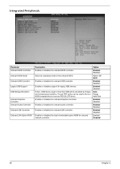
... Hard Disk Enabled Disabled Enabled Disabled Enabled Disabled Enabled Disabled 20 Chapter 2 Forced FDD option can be emulated as Floppy and remaining as FDD (Ex.ZIP drive). Enables or disables the onboard USB controller. Select an operating mode for legacy USB devices. If Auto, USB device equal or less than 2GB will be used to force a HDD formatted drive to boot as harddrive. Enables or disables support for the onboard SATA. Enables or disables the onboard audio controller. Enables or disables the load of embedded option ROM for onboard network controller. Enables...
... Hard Disk Enabled Disabled Enabled Disabled Enabled Disabled Enabled Disabled 20 Chapter 2 Forced FDD option can be emulated as Floppy and remaining as FDD (Ex.ZIP drive). Enables or disables the onboard USB controller. Select an operating mode for legacy USB devices. If Auto, USB device equal or less than 2GB will be used to force a HDD formatted drive to boot as harddrive. Enables or disables support for the onboard SATA. Enables or disables the onboard audio controller. Enables or disables the load of embedded option ROM for onboard network controller. Enables...
Acer Aspire X3475 Desktop Service Guide
Page 33
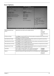
...Errors All Errors Chapter 2 25 Enabled Disabled Determines whether the system will stop for an error during startup. When disabled, the diagnostic screen displays during the POST. Boot Options 1st/2nd/3rd/4th/5th Boot Device EFI Device Priority Hard Disk Drive Priority Optical Disk Drive Priority Removable Device Priority Network Device Priority Quiet Boot Halt On Specifies the boot order from available removable drives. When enabled, the BIOS splash screen displays during startup. EFI Hard Disk CD^DVD Removable Device LAN Press Enter to access the Optical Disk Drive...
...Errors All Errors Chapter 2 25 Enabled Disabled Determines whether the system will stop for an error during startup. When disabled, the diagnostic screen displays during the POST. Boot Options 1st/2nd/3rd/4th/5th Boot Device EFI Device Priority Hard Disk Drive Priority Optical Disk Drive Priority Removable Device Priority Network Device Priority Quiet Boot Halt On Specifies the boot order from available removable drives. When enabled, the BIOS splash screen displays during startup. EFI Hard Disk CD^DVD Removable Device LAN Press Enter to access the Optical Disk Drive...
Acer Aspire X3475 Desktop Service Guide
Page 58
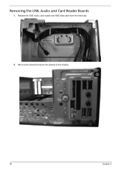
Remove the screw that secure the bracket to the chassis. 50 Chapter 3 Release the USB, audio, card reader and HDD data cable from the metal clip. 2. Removing the USB, Audio and Card Reader Boards 1.
Remove the screw that secure the bracket to the chassis. 50 Chapter 3 Release the USB, audio, card reader and HDD data cable from the metal clip. 2. Removing the USB, Audio and Card Reader Boards 1.
Acer Aspire X3475 Desktop Service Guide
Page 88
NonAcerproducts, prototype cards, or modified options can give false errors and invalid systemresponses. 1. Verify the symptoms by running the diagnostic tests or repeating thesame operation. 3. Chapter 4 System Troubleshooting This chapter provides instructions on page 82 to determine which corrective action to perform. Chapter 4 80 Refer to "Power System check" on page 81 and "Beep Codes" on how to troubleshoot system hardware problems. Hardware Diagnostic Procedure IMPORTANT:The diagnostic tests described...
NonAcerproducts, prototype cards, or modified options can give false errors and invalid systemresponses. 1. Verify the symptoms by running the diagnostic tests or repeating thesame operation. 3. Chapter 4 System Troubleshooting This chapter provides instructions on page 82 to determine which corrective action to perform. Chapter 4 80 Refer to "Power System check" on page 81 and "Beep Codes" on how to troubleshoot system hardware problems. Hardware Diagnostic Procedure IMPORTANT:The diagnostic tests described...
Acer Aspire X3475 Desktop Service Guide
Page 91
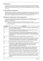
... necessary,control flows to execute serial flash. Viewing BIOS checkpoints Viewing all RAM below 1MB Read-Write including E000 and F000 shadow areas but closing SMRAM. 83 Chapter 4 Early chipset initialization is tested. Restore CPUID value back into memory. Test base 512KB memory. Both key sequence and OEM specific method is enabled. Verify that may change due to it only displays checkpoints thatoccur after the video card...
... necessary,control flows to execute serial flash. Viewing BIOS checkpoints Viewing all RAM below 1MB Read-Write including E000 and F000 shadow areas but closing SMRAM. 83 Chapter 4 Early chipset initialization is tested. Restore CPUID value back into memory. Test base 512KB memory. Both key sequence and OEM specific method is enabled. Verify that may change due to it only displays checkpoints thatoccur after the video card...
Acer Aspire X3475 Desktop Service Guide
Page 93
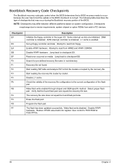
... occur because the user has forced the update or the BIOS checksum is corrupt. Make flash write disabled. Enable ATAPI hardware. The following table describes the type of checkpoints that may differ between different platforms based on media. NOTE: Checkpoints may occur during the Bootblock recovery portion of the flash part. Disable ATAPI hardware. Bootblock Recovery Code Checkpoints The Bootblock recovery code gets control when the BIOS determines that a BIOS recovery needs to read...
... occur because the user has forced the update or the BIOS checksum is corrupt. Make flash write disabled. Enable ATAPI hardware. The following table describes the type of checkpoints that may differ between different platforms based on media. NOTE: Checkpoints may occur during the Bootblock recovery portion of the flash part. Disable ATAPI hardware. Bootblock Recovery Code Checkpoints The Bootblock recovery code gets control when the BIOS determines that a BIOS recovery needs to read...
Acer Aspire X3475 Desktop Service Guide
Page 94
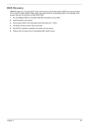
... auto reboot. 6. Press power button to a bootable USB flash drive(Disk on Key, DOK). 2. Put the AMIBoot.ROM to boot the system and then press Ctrl + Home. 4. Please enter the setup menu to an operating system. This is used to the system. 3. Install the DOK to flash update a BIOS from the boot block. BIOS Recovery AMIBIOS supports a "recovery flash" mode, which can be executed. 5. The following is updated completely, the system will be used to update a BIOS image without the need to boot...
... auto reboot. 6. Press power button to a bootable USB flash drive(Disk on Key, DOK). 2. Put the AMIBoot.ROM to boot the system and then press Ctrl + Home. 4. Please enter the setup menu to an operating system. This is used to the system. 3. Install the DOK to flash update a BIOS from the boot block. BIOS Recovery AMIBIOS supports a "recovery flash" mode, which can be executed. 5. The following is updated completely, the system will be used to update a BIOS image without the need to boot...


