Aspire X1700 / Veriton X270 Service Guide
Page 6
...customer machines. add-on your regional web or channel. These LOCALIZED FEATURES will not be covered in this printed Service Guide. For ACER-AUTHORIZED SERVICE PROVIDERS, your regional office MAY have a DIFFERENT part number code to extend the functionality of this generic service guide....by your regional offices or the responsible personnel/channel to -date information available on card, modem, or extra memory capability). In such cases, please contact your regional Acer office to the BASIC CONFIGURATION decided for whatever reason, a part number change is made, it will NOT...
...customer machines. add-on your regional web or channel. These LOCALIZED FEATURES will not be covered in this printed Service Guide. For ACER-AUTHORIZED SERVICE PROVIDERS, your regional office MAY have a DIFFERENT part number code to extend the functionality of this generic service guide....by your regional offices or the responsible personnel/channel to -date information available on card, modem, or extra memory capability). In such cases, please contact your regional Acer office to the BASIC CONFIGURATION decided for whatever reason, a part number change is made, it will NOT...
Aspire X1700 / Veriton X270 Service Guide
Page 7
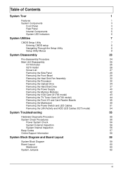
... CMOS setup 8 Navigating Through the Setup Utility 8 Setup Utility Menus 9 System Disassembly 23 Pre-disassembly Procedure 24 Main Unit Disassembly 25 X1700 model 25 X270 model 26 Screw List 27 Removing the Side Panel 28 Removing the Front Bezel 29 Removing the Heat Sink Fan Assembly ... Optical Drive 34 Removing the Hard Disk Drive 37 Removing the Power Supply 40 Removing the Memory Modules 42 Removing the VGA Card (X1700 model) 43 Removing the TV Tuner Card (X1700 model) 44 Removing the Front I/O and Card Reader Boards 45 Removing the Mainboard 49 Removing...
... CMOS setup 8 Navigating Through the Setup Utility 8 Setup Utility Menus 9 System Disassembly 23 Pre-disassembly Procedure 24 Main Unit Disassembly 25 X1700 model 25 X270 model 26 Screw List 27 Removing the Side Panel 28 Removing the Front Bezel 29 Removing the Heat Sink Fan Assembly ... Optical Drive 34 Removing the Hard Disk Drive 37 Removing the Power Supply 40 Removing the Memory Modules 42 Removing the VGA Card (X1700 model) 43 Removing the TV Tuner Card (X1700 model) 44 Removing the Front I/O and Card Reader Boards 45 Removing the Mainboard 49 Removing...
Aspire X1700 / Veriton X270 Service Guide
Page 9
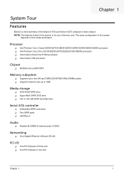
... Dual-Core E1200 processor Intel Celeron 450 processor Chipset NVIDIA nForce MCP73PV Memory subsystem Supports up to two 240-pin DDR2-533/667/800 MHz DIMM sockets Supports memory size up to 4GB Media storage DVD-ROM SATA drive Super-Multi SATA...45) PCI I/O One PCI Express x16 bus slot One PCI Express x1 bus slot Chapter 1 1 The exact configuration of the Aspire X1700 and Veriton X270 computer's many feature: NOTE: The features listed in this section is a brief summary of the system depends on the model purchased.
... Dual-Core E1200 processor Intel Celeron 450 processor Chipset NVIDIA nForce MCP73PV Memory subsystem Supports up to two 240-pin DDR2-533/667/800 MHz DIMM sockets Supports memory size up to 4GB Media storage DVD-ROM SATA drive Super-Multi SATA...45) PCI I/O One PCI Express x16 bus slot One PCI Express x1 bus slot Chapter 1 1 The exact configuration of the Aspire X1700 and Veriton X270 computer's many feature: NOTE: The features listed in this section is a brief summary of the system depends on the model purchased.
Aspire X1700 / Veriton X270 Service Guide
Page 10
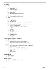
I/O ports Front Three USB 2.0 ports Memory Stick Memory Stick PRO Secure Digital (SD) Card miniSD Card Headphone/speaker-out/line-out jack Microphone-in jack ...; Genuine Windows Vista® Ultimate (32/64-bit) Genuine Windows Vista Home Premium (32/64-bit) Applications Acer Empowering Technology (Acer eRecovery Management) Acer Arcade Live McAfee Internet Security Suite 2008 Trial version Adobe Reader eSobi NTI MediaMaker System BIOS ...
I/O ports Front Three USB 2.0 ports Memory Stick Memory Stick PRO Secure Digital (SD) Card miniSD Card Headphone/speaker-out/line-out jack Microphone-in jack ...; Genuine Windows Vista® Ultimate (32/64-bit) Genuine Windows Vista Home Premium (32/64-bit) Applications Acer Empowering Technology (Acer eRecovery Management) Acer Arcade Live McAfee Internet Security Suite 2008 Trial version Adobe Reader eSobi NTI MediaMaker System BIOS ...
Aspire X1700 / Veriton X270 Service Guide
Page 15
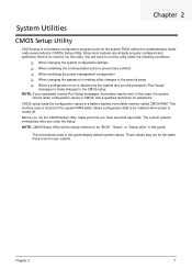
...is a hardware configuration program built into the system ROM, called CMOS RAM. CMOS setup loads the configuration values in a battery-backed nonvolatile memory called the complementary metaloxide semiconductor (CMOS) Setup Utility. Before you run the CMOS Setup Utility, make changes to the CMOS setup NOTE: ... you have saved all open files. These values may be the same those found in CMOS. The screenshots used in this utility. This memory area is not part of the system RAM which allows configuration data to the security setup When a configuration error is turned off...
...is a hardware configuration program built into the system ROM, called CMOS RAM. CMOS setup loads the configuration values in a battery-backed nonvolatile memory called the complementary metaloxide semiconductor (CMOS) Setup Utility. Before you run the CMOS Setup Utility, make changes to the CMOS setup NOTE: ... you have saved all open files. These values may be the same those found in CMOS. The screenshots used in this utility. This memory area is not part of the system RAM which allows configuration data to the security setup When a configuration error is turned off...

Aspire X1700 / Veriton X270 Service Guide
Page 18
...Chapter 2 Serial number of the system. These entries are for your reference only and are not user-configurable. Version number of system memory installed on the system. Total size of the BIOS setup utility. Speed of CPU installed on the system. Parameter Processor Type Processor Speed ...System Memory System Manufacturer Product Name System Serial Number System BIOS Version BIOS Release Date Asset Tag Number Description Type of the CPU installed on...
...Chapter 2 Serial number of the system. These entries are for your reference only and are not user-configurable. Version number of system memory installed on the system. Total size of the BIOS setup utility. Speed of CPU installed on the system. Parameter Processor Type Processor Speed ...System Memory System Manufacturer Product Name System Serial Number System BIOS Version BIOS Release Date Asset Tag Number Description Type of the CPU installed on...

Aspire X1700 / Veriton X270 Service Guide
Page 21
...change the setting. Enables or disables the Virtualization Technology (VT) availability. Enables or disables remapping of overlapped PCI memory above the total physical memory. When disabled, the system operates at maximum CPU speed. If enabled, a virtual machine manager (VMM) can... 2 13 Enables or disabled dual display support. Advanced Chipset Features Parameter Intel EIST Intel XD Bit Intel Virtualization Technology Memory Hole Remapping Dual Displays Support Primary Video Description When enabled, this technology. When enabled, the processor disables code execution ...
...change the setting. Enables or disables the Virtualization Technology (VT) availability. Enables or disables remapping of overlapped PCI memory above the total physical memory. When disabled, the system operates at maximum CPU speed. If enabled, a virtual machine manager (VMM) can... 2 13 Enables or disabled dual display support. Advanced Chipset Features Parameter Intel EIST Intel XD Bit Intel Virtualization Technology Memory Hole Remapping Dual Displays Support Primary Video Description When enabled, this technology. When enabled, the processor disables code execution ...

Aspire X1700 / Veriton X270 Service Guide
Page 27
Load Default Settings The Load Default Settings menu allows you choose to load the default settings for all BIOS setup parameters. Chapter 2 19 If you are quite demanding in terms of low-performance components and you to load these settings, the system might not function properly. Setup defaults are using low-speed memory chips or other kinds of resources consumption.
Load Default Settings The Load Default Settings menu allows you choose to load the default settings for all BIOS setup parameters. Chapter 2 19 If you are quite demanding in terms of low-performance components and you to load these settings, the system might not function properly. Setup defaults are using low-speed memory chips or other kinds of resources consumption.
Aspire X1700 / Veriton X270 Service Guide
Page 33
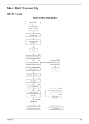
Main Unit Disassembly X1700 model MAIN UNIT DISASSEMBLY MAIN UNIT Ax2 SIDE PANEL FRONT BEZEL HEAT SINK FAN ASSEMBLY CPU Bx1 OPTICAL DISK DRIVE Cx1 HDD-ODD BRACKET Ax3, Cx1 POWER SUPPLY MEMORY MODULES Ex1 VGA CARD Ex1 TV TUNER CARD Dx2 FRONT I/O AND CARD READER BOARD BRACKET Bx1, Cx6 MAINBOARD Cx1 POWER SWITCH AND LED CABLE BRACKET Dx4 HDD MODULE HDD Cx2 FRONT I/O BOARD Cx2 CARD READER BOARD POWER SWITCH AND LED CABLES Chapter 3 25
Main Unit Disassembly X1700 model MAIN UNIT DISASSEMBLY MAIN UNIT Ax2 SIDE PANEL FRONT BEZEL HEAT SINK FAN ASSEMBLY CPU Bx1 OPTICAL DISK DRIVE Cx1 HDD-ODD BRACKET Ax3, Cx1 POWER SUPPLY MEMORY MODULES Ex1 VGA CARD Ex1 TV TUNER CARD Dx2 FRONT I/O AND CARD READER BOARD BRACKET Bx1, Cx6 MAINBOARD Cx1 POWER SWITCH AND LED CABLE BRACKET Dx4 HDD MODULE HDD Cx2 FRONT I/O BOARD Cx2 CARD READER BOARD POWER SWITCH AND LED CABLES Chapter 3 25
Aspire X1700 / Veriton X270 Service Guide
Page 34
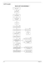
X270 model MAIN UNIT DISASSEMBLY MAIN UNIT Ax2 SIDE PANEL FRONT BEZEL HEAT SINK FAN ASSEMBLY CPU Bx1 OPTICAL DISK DRIVE HDD-ODD BRACKET Ax3, Cx1 POWER SUPPLY MEMORY MODULES Dx2 FRONT I/O AND CARD READER BOARD BRACKET Bx1, Cx6 MAINBOARD Cx1 POWER SWITCH AND LED CABLE BRACKET LAN ACTIVITY AND HDD LED CABLE BRACKET Dx4 HDD MODULE HDD Cx2 FRONT I/O BOARD Cx2 CARD READER BOARD POWER SWITCH AND LED CABLES LAN ACTIVITY AND HDD LED CABLES 26 Chapter 3
X270 model MAIN UNIT DISASSEMBLY MAIN UNIT Ax2 SIDE PANEL FRONT BEZEL HEAT SINK FAN ASSEMBLY CPU Bx1 OPTICAL DISK DRIVE HDD-ODD BRACKET Ax3, Cx1 POWER SUPPLY MEMORY MODULES Dx2 FRONT I/O AND CARD READER BOARD BRACKET Bx1, Cx6 MAINBOARD Cx1 POWER SWITCH AND LED CABLE BRACKET LAN ACTIVITY AND HDD LED CABLE BRACKET Dx4 HDD MODULE HDD Cx2 FRONT I/O BOARD Cx2 CARD READER BOARD POWER SWITCH AND LED CABLES LAN ACTIVITY AND HDD LED CABLES 26 Chapter 3

Aspire X1700 / Veriton X270 Service Guide
Page 50
... IMPORTANT:Before removing any DIMM from the memory board, make sure to create a backup file of the DIMM slot outward to pull it away from the chassis (2). Press the holding clips on both ... "Removing the Front Bezel" on page 28. 2. See "Removing the Side Panel" on page 29. 3. See "Removing the Heat Sink Fan Assembly" on page 34. 6. X1700 model X270 model 42 Chapter 3 See "Removing the Optical Drive" on page 30. 4.
... IMPORTANT:Before removing any DIMM from the memory board, make sure to create a backup file of the DIMM slot outward to pull it away from the chassis (2). Press the holding clips on both ... "Removing the Front Bezel" on page 28. 2. See "Removing the Side Panel" on page 29. 3. See "Removing the Heat Sink Fan Assembly" on page 34. 6. X1700 model X270 model 42 Chapter 3 See "Removing the Optical Drive" on page 30. 4.

Aspire X1700 / Veriton X270 Service Guide
Page 53
Removing the Front I /O and card reader boards. See "Removing the Side Panel" on page 37. 7. See "Removing the Hard Disk Drive" on page 28. 2. X1700 model 9. See "Removing the Processor" on page 29. 3. See "Removing the Front Bezel" on page 32. 5. Open the cable retention clip. See "Removing the Heat Sink Fan Assembly" on page 42. 8. See "Removing the Memory Modules" on page 30. 4. See "Removing the Optical Drive" on page 34. 6. Disconnect one end of the USB, 1394, and audio cables from the I /O and Card Reader Boards 1. X270 model Chapter 3 45
Removing the Front I /O and card reader boards. See "Removing the Side Panel" on page 37. 7. See "Removing the Hard Disk Drive" on page 28. 2. X1700 model 9. See "Removing the Processor" on page 29. 3. See "Removing the Front Bezel" on page 32. 5. Open the cable retention clip. See "Removing the Heat Sink Fan Assembly" on page 42. 8. See "Removing the Memory Modules" on page 30. 4. See "Removing the Optical Drive" on page 34. 6. Disconnect one end of the USB, 1394, and audio cables from the I /O and Card Reader Boards 1. X270 model Chapter 3 45

Aspire X1700 / Veriton X270 Service Guide
Page 57
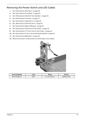
.... 6. See "Removing the Optical Drive" on page 29. 3. Remove the screw (B) on page 44. 10. See "Removing the TV Tuner Card (X1700 model)" on the rear panel. See "Removing the Memory Modules" on page 37. 7. Screw (Quantity) M3xL5 (1) Color Black Torque 5.5 to 6.5 kgf-cm Part No. 86.1A324.5R0 Chapter 3 49 Disconnect...
.... 6. See "Removing the Optical Drive" on page 29. 3. Remove the screw (B) on page 44. 10. See "Removing the TV Tuner Card (X1700 model)" on the rear panel. See "Removing the Memory Modules" on page 37. 7. Screw (Quantity) M3xL5 (1) Color Black Torque 5.5 to 6.5 kgf-cm Part No. 86.1A324.5R0 Chapter 3 49 Disconnect...
Aspire X1700 / Veriton X270 Service Guide
Page 59
See "Removing the Side Panel" on page 42. 8. See "Removing the Memory Modules" on page 28. 2. See "Removing the Front I/O and Card Reader Boards" on page 32. 5. See "Removing the ...34. 6. See "Removing the Optical Drive" on page 30. 4. Removing the Power Switch and LED Cables 1. See "Removing the VGA Card (X1700 model)" on page 49. 12. See "Removing the Mainboard" on page 43. 9. Remove the screw (C) that secures the LED bracket to ... page 37. 7. See "Removing the Hard Disk Drive" on page 29. 3. See "Removing the TV Tuner Card (X1700 model)" on page 44. 10.
See "Removing the Side Panel" on page 42. 8. See "Removing the Memory Modules" on page 28. 2. See "Removing the Front I/O and Card Reader Boards" on page 32. 5. See "Removing the ...34. 6. See "Removing the Optical Drive" on page 30. 4. Removing the Power Switch and LED Cables 1. See "Removing the VGA Card (X1700 model)" on page 49. 12. See "Removing the Mainboard" on page 43. 9. Remove the screw (C) that secures the LED bracket to ... page 37. 7. See "Removing the Hard Disk Drive" on page 29. 3. See "Removing the TV Tuner Card (X1700 model)" on page 44. 10.
Aspire X1700 / Veriton X270 Service Guide
Page 62
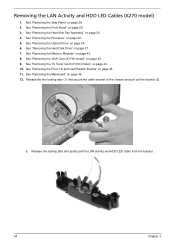
... the bracket (2). Removing the LAN Activity and HDD LED Cables (X270 model) 1. See "Removing the Front Bezel" on page 43. 9. See "Removing the VGA Card (X1700 model)" on page 29. 3. See "Removing the Optical Drive" on page 45. 11. See "Removing the Front I/O and Card Reader Boards" on page 34. 6. .... 2. Release the locking tabs and gently pull the LAN activity and HDD LED cable from the bracket. 54 Chapter 3 See "Removing the TV Tuner Card (X1700 model)" on page 42. 8. See "Removing the Memory Modules" on page 44. 10. See "Removing the Mainboard" on page 49. 12. c.
... the bracket (2). Removing the LAN Activity and HDD LED Cables (X270 model) 1. See "Removing the Front Bezel" on page 43. 9. See "Removing the VGA Card (X1700 model)" on page 29. 3. See "Removing the Optical Drive" on page 45. 11. See "Removing the Front I/O and Card Reader Boards" on page 34. 6. .... 2. Release the locking tabs and gently pull the LAN activity and HDD LED cable from the bracket. 54 Chapter 3 See "Removing the TV Tuner Card (X1700 model)" on page 42. 8. See "Removing the Memory Modules" on page 44. 10. See "Removing the Mainboard" on page 49. 12. c.
Aspire X1700 / Veriton X270 Service Guide
Page 65
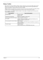
... occur after the video card has been activated. VGA not installed or VGA error. Not all computers using AMIBIOS enable this feature. Memory not installed or memory error. Graphics card error/not installed, graphics card memory error or graphics card BIOS checksum error. BIOS damaged. CMOS checksum error or CMOS battery loss occurs.
... occur after the video card has been activated. VGA not installed or VGA error. Not all computers using AMIBIOS enable this feature. Memory not installed or memory error. Graphics card error/not installed, graphics card memory error or graphics card BIOS checksum error. BIOS damaged. CMOS checksum error or CMOS battery loss occurs.
Aspire X1700 / Veriton X270 Service Guide
Page 69
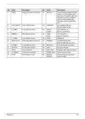
... Port Bottom: PS2 Keyboard Port 18 ATX12V1 4-pin ATX power connector 19 CPU1 Processor socket 20 CPU_FAN Processor fan cable connector 21 DIMM1 and 2 System memory slots 22 GPIO33 GPIO32 General Purpose Input and Output jumper Chapter 5 61
... Port Bottom: PS2 Keyboard Port 18 ATX12V1 4-pin ATX power connector 19 CPU1 Processor socket 20 CPU_FAN Processor fan cable connector 21 DIMM1 and 2 System memory slots 22 GPIO33 GPIO32 General Purpose Input and Output jumper Chapter 5 61
Aspire X1700 / Veriton X270 Service Guide
Page 96
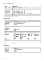
System Board Major Chips Item System core logic Memory controller Storage controller Video controller PCI controller LAN controller Audio controller Super I/O controller Specification NVIDIA NForce MCP73PV 1048 BGA NVIDIA NForce MCP73PV ...NForce MCP73PV 1048 BGA NVIDIA NForce MCP73PV 1048 BGA + Realtek RTL8211C Realtek ALC888S ITE IT8718 GX System Memory Item Memory controller Memory type Module name Organization Pin count DIMM sockets DIMM size Minimum memory Maximum memory Vendor Model name Type DIMM size (GB) Module structure Pin System BIOS Specification NVIDIA NForce MCP73PV 1048...
System Board Major Chips Item System core logic Memory controller Storage controller Video controller PCI controller LAN controller Audio controller Super I/O controller Specification NVIDIA NForce MCP73PV 1048 BGA NVIDIA NForce MCP73PV ...NForce MCP73PV 1048 BGA NVIDIA NForce MCP73PV 1048 BGA + Realtek RTL8211C Realtek ALC888S ITE IT8718 GX System Memory Item Memory controller Memory type Module name Organization Pin count DIMM sockets DIMM size Minimum memory Maximum memory Vendor Model name Type DIMM size (GB) Module structure Pin System BIOS Specification NVIDIA NForce MCP73PV 1048...


