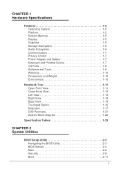
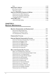
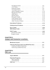
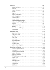
Acer Aspire V5 14 - 431
Acer Aspire V5 14

View Results Below
Free Acer Aspire V5-431 manuals!
Problems with Acer Aspire V5-431?
Ask a Question
Free Acer Aspire V5-431 manuals!
Problems with Acer Aspire V5-431?
Ask a Question
Related Manual Pages

Related Videos

Acer Aspire V5 14-Inch Subnotebook Hands On (English)
Duration: 1:32
Total Views: 12,554
Duration: 1:32
Total Views: 12,554
Acer Aspire V5-471P 14" Notebook (Silver)
Duration: 1:21
Total Views: 3,609
Duration: 1:21
Total Views: 3,609
Acer Aspire V5 im Hands mit 14 Zoll
Duration: 1:24
Total Views: 3,658
Duration: 1:24
Total Views: 3,658
Acer Aspire V5 14-Inch Subnotebook Hands On (Deutsch)
Duration: 1:25
Total Views: 3,246
Duration: 1:25
Total Views: 3,246
Acer Aspire V5-471
Duration: :59
Total Views: 12,455
Duration: :59
Total Views: 12,455
Similar Questions

Anyone Have An Sis M760gx Driver For Ubuntu/peppermint 14.4 ????? Acer 5003wlmi
After installation of Peppermint 5 (fast UBUNTU 4.4 w LX), icons don't display, display background d...
After installation of Peppermint 5 (fast UBUNTU 4.4 w LX), icons don't display, display background d...
(Posted by harris898 8 years ago)

Can Acer Aspire V5 431 Play Game Such As A Pes 2013/14?
i mean,,,i already download pes 2013 but can opened...can you help me to solve this problem.....or t...
i mean,,,i already download pes 2013 but can opened...can you help me to solve this problem.....or t...
(Posted by alifiqhmal 10 years ago)

Which 13 To 14 Inch Acer Laptop Is Fully Linux Compatible
(Posted by yniazila 11 years ago)
Aspire 9410-4441 Which Batter, 11 Volt Or The 14 Volt.
see the title for question
see the title for question
(Posted by noles59 11 years ago)
Related Terms
The following terms were also used when searching for Acer Aspire V5 14 - 431:- acer aspire v5
- acer aspire v5 - 431
- acer aspire v5 11.6
- acer aspire v5 14
- acer aspire v5 4 series
- acer aspire v5 431
- acer aspire v5 431 14
- acer aspire v5 431 471
- acer aspire v5 431 4899
- acer aspire v5 431 8gb
- acer aspire v5 431 amazon
- acer aspire v5 431 battery
- acer aspire v5 431 battery price
- acer aspire v5 431 best price
- acer aspire v5 431 bios
- acer aspire v5 431 bios update
- acer aspire v5 431 body
- acer aspire v5 431 boot menu key
- acer aspire v5 431 camera driver
- acer aspire v5 431 charger
- acer aspire v5 431 driver
- acer aspire v5 431 driver download
- acer aspire v5 431 driver download win7
- acer aspire v5 431 drivers
- acer aspire v5 431 drivers for windows 7
- acer aspire v5 431 drivers for windows 7 32bit
- acer aspire v5 431 ethernet port
- acer aspire v5 431 hard drive replacement
- acer aspire v5 431 keyboard
- acer aspire v5 431 laptop
- acer aspire v5 431 laptop price
- acer aspire v5 431 laptop review
- acer aspire v5 431 laptop reviews
- acer aspire v5 431 manual
- acer aspire v5 431 motherboard
- acer aspire v5 431 ms2360
- acer aspire v5 431 precio
- acer aspire v5 431 price
- acer aspire v5 431 price in india
- acer aspire v5 431 ram slot
- acer aspire v5 431 recovery drive
- acer aspire v5 431 review
- acer aspire v5 431 review cnet
- acer aspire v5 431 reviews
- acer aspire v5 431 screen
- acer aspire v5 431 screen replacement
- acer aspire v5 431 series
- acer aspire v5 431 spec
- acer aspire v5 431 specification
- acer aspire v5 431 specs
- acer aspire v5 431 ssd
- acer aspire v5 431 touch screen
- acer aspire v5 431 windows 7 driver
- acer aspire v5 431 windows 8
- acer aspire v5 431-4899
- acer aspire v5 431/471
- acer aspire v5 431p
- acer aspire v5 471
- acer aspire v5 531 4636
- acer aspire v5 571 6605
- acer aspire v5 laptop
- acer aspire v5 laptop review
- acer aspire v5 review
- acer aspire v5 series notebook computer
- acer aspire v5 specs
- acer aspire v5 touch
- acer aspire v5-431
- acer aspire v5-431 14 inch
- acer aspire v5-431 14 keyboard replacement
- acer aspire v5-431 14-inch laptop
- acer aspire v5-431 8gb
- acer aspire v5-431 amazon
- acer aspire v5-431 battery
- acer aspire v5-431 battery removal
- acer aspire v5-431 bios
- acer aspire v5-431 bios key
- acer aspire v5-431 bios password reset
- acer aspire v5-431 black screen
- acer aspire v5-431 bluetooth driver
- acer aspire v5-431 charger
- acer aspire v5-431 configuration
- acer aspire v5-431 disassembly
- acer aspire v5-431 driver
- acer aspire v5-431 drivers
- acer aspire v5-431 drivers download
- acer aspire v5-431 drivers for windows 7
- acer aspire v5-431 drivers windows 10
- acer aspire v5-431 factory reset
- acer aspire v5-431 factory restore
- acer aspire v5-431 hard disk replacement
- acer aspire v5-431 hard drive removal
- acer aspire v5-431 hard drive replacement
- acer aspire v5-431 keyboard
- acer aspire v5-431 keyboard replacement
- acer aspire v5-431 laptop
- acer aspire v5-431 laptop review
- acer aspire v5-431 lcd back cover
- acer aspire v5-431 manual
- acer aspire v5-431 model ms2360
- acer aspire v5-431 motherboard
- acer aspire v5-431 ms2360
- acer aspire v5-431 parts
- acer aspire v5-431 price
- acer aspire v5-431 price in india
- acer aspire v5-431 price in malaysia
- acer aspire v5-431 processor upgrade
- acer aspire v5-431 recovery key
- acer aspire v5-431 restore disk
- acer aspire v5-431 review
- acer aspire v5-431 review cnet
- acer aspire v5-431 reviews
- acer aspire v5-431 screen
- acer aspire v5-431 screen replacement
- acer aspire v5-431 series
- acer aspire v5-431 service guide
- acer aspire v5-431 specification
- acer aspire v5-431 specifications
- acer aspire v5-431 specs
- acer aspire v5-431 touchpad not working
- acer aspire v5-431 webcam driver
- acer aspire v5-431 webcam not working
- acer aspire v5-431 weight
- acer aspire v5-431 wifi driver
- acer aspire v5-431 windows 8
- acer aspire v5-431-14
- acer aspire v5-431-14 laptop
- acer aspire v5-431-4899
- acer aspire v5-431/471
- acer aspire v5-431/v5-471
- acer aspire v5-431p
- acer aspire v5-431p-987b4g50mass
- acer aspire v5-531-4636
- acer aspire v5-571
- aspire v5
- aspire v5 - 431
- aspire v5 -431
- aspire v5 -471
- aspire v5 11.6
- aspire v5 11.6 review
- aspire v5 122p
- aspire v5 122p 0408
- aspire v5 14 inch
- aspire v5 15.6
- aspire v5 171
- aspire v5 431
- aspire v5 431 14
- aspire v5 431 471
- aspire v5 431 4899
- aspire v5 431 8gb
- aspire v5 431 amazon
- aspire v5 431 battery
- aspire v5 431 battery price
- aspire v5 431 best price
- aspire v5 431 bios
- aspire v5 431 bios update
- aspire v5 431 bluetooth driver
- aspire v5 431 body
- aspire v5 431 boot menu key
- aspire v5 431 camera driver
- aspire v5 431 charger
- aspire v5 431 driver
- aspire v5 431 driver download
- aspire v5 431 driver download win7
- aspire v5 431 drivers
- aspire v5 431 drivers for windows 7
- aspire v5 431 drivers for windows 7 32bit
- aspire v5 431 drivers windows 10
- aspire v5 431 ethernet port
- aspire v5 431 hard drive replacement
- aspire v5 431 how to remove battery
- aspire v5 431 keyboard
- aspire v5 431 lan connection
- aspire v5 431 laptop
- aspire v5 431 laptop price
- aspire v5 431 laptop review
- aspire v5 431 laptop reviews
- aspire v5 431 manual
- aspire v5 431 memory
- aspire v5 431 motherboard
- aspire v5 431 ms2360
- aspire v5 431 precio
- aspire v5 431 price
- aspire v5 431 price in india
- aspire v5 431 ram slot
- aspire v5 431 recovery drive
- aspire v5 431 review
- aspire v5 431 review cnet
- aspire v5 431 reviews
- aspire v5 431 screen
- aspire v5 431 screen replacement
- aspire v5 431 series
- aspire v5 431 series driver
- aspire v5 431 spec
- aspire v5 431 specification
- aspire v5 431 specs
- aspire v5 431 ssd
- aspire v5 431 touch screen
- aspire v5 431 wifi driver
- aspire v5 431 windows 7 driver
- aspire v5 431 windows 8
- aspire v5 431 wireless driver
- aspire v5 431-4899
- aspire v5 431/471
- aspire v5 431p
- aspire v5 471
- aspire v5 471 6473
- aspire v5 471 keyboard replace
- aspire v5 471g
- aspire v5 531 4636
- aspire v5 571
- aspire v5 571 6726
- aspire v5 571 6869
- aspire v5 571 p user manual
- aspire v5 571-6869
- aspire v5 571p
- aspire v5 acer
- aspire v5 battery
- aspire v5 battery life
- aspire v5 best buy
- aspire v5 bios
- aspire v5 black screen
- aspire v5 boot from usb
- aspire v5 boot menu
- aspire v5 charger
- aspire v5 drivers
- aspire v5 i3
- aspire v5 laptop
- aspire v5 laptop windows 8
- aspire v5 notebook
- aspire v5 price
- aspire v5 review
- aspire v5 reviews
- aspire v5 series
- aspire v5 series notebook
- aspire v5 slim
- aspire v5 specs
- aspire v5 touch
- aspire v5 touch 15.6
- aspire v5 touch battery removal
- aspire v5 touch best buy
- aspire v5 touch pad
- aspire v5 touch price
- aspire v5 touch screen
- aspire v5 touch screen 11.6
- aspire v5 touch screen laptop
- aspire v5 touch screen replacement
- aspire v5 user manual
- aspire v5 user's manual
- aspire v5 users manual
- aspire v5 webcam driver
- aspire v5-122p
- aspire v5-122p-0408
- aspire v5-122p-0646
- aspire v5-122p-0864
- aspire v5-123
- aspire v5-132p
- aspire v5-171
- aspire v5-431
- aspire v5-431 14 inch
- aspire v5-431 14 keyboard replacement
- aspire v5-431 14-inch laptop
- aspire v5-431 8gb
- aspire v5-431 acer
- aspire v5-431 amazon
- aspire v5-431 battery
- aspire v5-431 battery price
- aspire v5-431 battery removal
- aspire v5-431 bios
- aspire v5-431 bios key
- aspire v5-431 bios password reset
- aspire v5-431 bios setup
- aspire v5-431 black screen
- aspire v5-431 bluetooth driver
- aspire v5-431 boot menu
- aspire v5-431 charger
- aspire v5-431 configuration
- aspire v5-431 disassembly
- aspire v5-431 driver
- aspire v5-431 driver download
- aspire v5-431 driver for windows 7
- aspire v5-431 driver for windows 7 32bit
- aspire v5-431 driver for windows 7 64 bit
- aspire v5-431 driver for windows 8
- aspire v5-431 driver xp
- aspire v5-431 drivers
- aspire v5-431 drivers download
- aspire v5-431 drivers for windows 7
- aspire v5-431 drivers windows 10
- aspire v5-431 factory reset
- aspire v5-431 factory restore
- aspire v5-431 hard disk replacement
- aspire v5-431 hard drive removal
- aspire v5-431 hard drive replacement
- aspire v5-431 keyboard
- aspire v5-431 keyboard replacement
- aspire v5-431 laptop
- aspire v5-431 lcd back cover
- aspire v5-431 manual
- aspire v5-431 memory
- aspire v5-431 model ms2360
- aspire v5-431 motherboard
- aspire v5-431 ms2360
- aspire v5-431 parts
- aspire v5-431 price
- aspire v5-431 price in india
- aspire v5-431 price in malaysia
- aspire v5-431 price malaysia
- aspire v5-431 processor
- aspire v5-431 processor upgrade
- aspire v5-431 ram
- aspire v5-431 ram upgrade
- aspire v5-431 recovery
- aspire v5-431 recovery key
- aspire v5-431 restore disk
- aspire v5-431 review
- aspire v5-431 review cnet
- aspire v5-431 reviews
- aspire v5-431 screen
- aspire v5-431 screen replacement
- aspire v5-431 series
- aspire v5-431 series specs
- aspire v5-431 service guide
- aspire v5-431 spec
- aspire v5-431 specification
- aspire v5-431 specifications
- aspire v5-431 specs
- aspire v5-431 touchpad not working
- aspire v5-431 webcam driver
- aspire v5-431 webcam not working
- aspire v5-431 weight
- aspire v5-431 wifi driver
- aspire v5-431 windows 7 driver
- aspire v5-431 windows 8
- aspire v5-431-14
- aspire v5-431-14 laptop
- aspire v5-431-4899
- aspire v5-431/471
- aspire v5-431/471 acer
- aspire v5-431/471 laptop
- aspire v5-431/v5-471
- aspire v5-431p
- aspire v5-431p-987b4g50mass
- aspire v5-471
- aspire v5-471g
- aspire v5-473pg
- aspire v5-531
- aspire v5-531p-4129
- aspire v5-551
- aspire v5-561p
- aspire v5-571
- aspire v5-571 drivers
- aspire v5-571 replacement screen
- aspire v5-571g
- aspire v5-571p
- aspire v5-571p-6464
- aspire v5-571p-6604
- aspire v5-571p-6648
- aspire v5-571pg
- aspire v5-572p
- aspire v5-573p-6486
- aspire v5-573pg
- driver acer aspire v5-431
- driver aspirev5-431
- laptop acer aspire v5-431