
Acer V5-471 Notebook Service Guide
Page 5
... Dimensions and Weight 1-10 Environment 1-10 Notebook Tour 1-11 Open Front View 1-11 Close Front View 1-12 Left View 1-13 Right View 1-14 Base View 1-15 Touchpad Basics 1-16 Keyboard 1-17 D2D Recovery 1-21 System Block Diagram 1-22 Specification Tables 1-23 CHAPTER 2 System Utilities BIOS Setup Utility 2-3 Navigating the BIOS Utility...
... Dimensions and Weight 1-10 Environment 1-10 Notebook Tour 1-11 Open Front View 1-11 Close Front View 1-12 Left View 1-13 Right View 1-14 Base View 1-15 Touchpad Basics 1-16 Keyboard 1-17 D2D Recovery 1-21 System Block Diagram 1-22 Specification Tables 1-23 CHAPTER 2 System Utilities BIOS Setup Utility 2-3 Navigating the BIOS Utility...
Acer V5-471 Notebook Service Guide
Page 6
Exit 2-12 BIOS Flash Utilities 2-13 DOS Flash Utility 2-14 WinFlash Utility 2-14 Remove HDD/BIOS Password Utilities 2-15 Removing the HDD Password 2-15 Removing the BIOS Passwords 2-16 Clearing the BIOS Passwords 2-17 Using DMI Tools 2-18 LAN EEPROM Utility 2-18 CHAPTER 3 ...Removing the Battery Pack 3-9 Removing the DIMM Cover 3-10 Removing the DIMM Modules 3-11 Removing the ODD Module 3-12 Removing the Keyboard 3-15 Main Unit Disassembly Process 3-17 Main Unit Disassembly Flowchart 3-17 Removing the Palmrest Module/Upper Case 3-18 Removing the Touchpad Board 3-21 Removing...
Exit 2-12 BIOS Flash Utilities 2-13 DOS Flash Utility 2-14 WinFlash Utility 2-14 Remove HDD/BIOS Password Utilities 2-15 Removing the HDD Password 2-15 Removing the BIOS Passwords 2-16 Clearing the BIOS Passwords 2-17 Using DMI Tools 2-18 LAN EEPROM Utility 2-18 CHAPTER 3 ...Removing the Battery Pack 3-9 Removing the DIMM Cover 3-10 Removing the DIMM Modules 3-11 Removing the ODD Module 3-12 Removing the Keyboard 3-15 Main Unit Disassembly Process 3-17 Main Unit Disassembly Flowchart 3-17 Removing the Palmrest Module/Upper Case 3-18 Removing the Touchpad Board 3-21 Removing...
Acer V5-471 Notebook Service Guide
Page 8
...Failure 4-7 Keyboard Failure 4-8 Touchpad Failure 4-9 Internal Speaker Failure 4-10 Microphone Failure 4-12 USB Failure 4-13 WLAN Failure 4-14 Bluetooth Failure 4-15 Card Reader Failure 4-16 Thermal Unit Failure 4-17 Other Functions Failure 4-18 Intermittent Problems 4-19 Undetermined Problems 4-19 Error Codes 4-20 BIOS Beep...Locations Mainboard Layout 5-3 Clearing Password Check and BIOS Recovery 5-7 Clearing the BIOS Passwords 5-7 Performing a BIOS Recovery 5-8 CHAPTER 6 FRU List Aspire MS2360 6-4 Exploded Diagrams 6-4 Main Assembly 6-4 LCD Assembly 6-6 FRU List 6-7 viii
...Failure 4-7 Keyboard Failure 4-8 Touchpad Failure 4-9 Internal Speaker Failure 4-10 Microphone Failure 4-12 USB Failure 4-13 WLAN Failure 4-14 Bluetooth Failure 4-15 Card Reader Failure 4-16 Thermal Unit Failure 4-17 Other Functions Failure 4-18 Intermittent Problems 4-19 Undetermined Problems 4-19 Error Codes 4-20 BIOS Beep...Locations Mainboard Layout 5-3 Clearing Password Check and BIOS Recovery 5-7 Clearing the BIOS Passwords 5-7 Performing a BIOS Recovery 5-8 CHAPTER 6 FRU List Aspire MS2360 6-4 Exploded Diagrams 6-4 Main Assembly 6-4 LCD Assembly 6-6 FRU List 6-7 viii
Acer V5-471 Notebook Service Guide
Page 12
... Dimensions and Weight 1-10 Environment 1-10 Notebook Tour 1-11 Open Front View 1-11 Close Front View 1-12 Left View 1-13 Right View 1-14 Base View 1-15 Touchpad Basics 1-16 Keyboard 1-17 D2D Recovery 1-21 System Block Diagram 1-22 Specification Tables 1-23 Computer Specifications 1-23 Processor 1-24 Processor Specifications 1-25 System Memory...
... Dimensions and Weight 1-10 Environment 1-10 Notebook Tour 1-11 Open Front View 1-11 Close Front View 1-12 Left View 1-13 Right View 1-14 Base View 1-15 Touchpad Basics 1-16 Keyboard 1-17 D2D Recovery 1-21 System Block Diagram 1-22 Specification Tables 1-23 Computer Specifications 1-23 Processor 1-24 Processor Specifications 1-25 System Memory...
Acer V5-471 Notebook Service Guide
Page 25
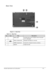
Base View No. Releases the battery for removal. 3 DIMM compartment Houses the computer's memory modules. 4 Speaker Outputs sounds. Base View Table 1-5. Base View 0 Figure 1-5. Icon Item 1 Battery pack 2 Battery release latch Description Provides power to the computer when the power cord is unplugged. Hardware Specifications and Configurations 1-15
Base View No. Releases the battery for removal. 3 DIMM compartment Houses the computer's memory modules. 4 Speaker Outputs sounds. Base View Table 1-5. Base View 0 Figure 1-5. Icon Item 1 Battery pack 2 Battery release latch Description Provides power to the computer when the power cord is unplugged. Hardware Specifications and Configurations 1-15

Acer V5-471 Notebook Service Guide
Page 33
... cm 0.78 in Weight (equipped with 6-cell 1.97 kg for UMA battery pack, HDD, and ODD) 2.01 kg for Discrete 4.343 lb for UMA 4.431 lb for Discrete Input power Operating voltage 19 V, 65 W Operating current (max) 3.42 A Temperature Operating (not writing to optical disc) 0 to 35 &#...to 60 °C -4 to 140 °F Relative humidity Operating 10% to 90% Nonoperating 5% to 95% Maximum altitude (unpressurized) Operating -15 to 3,048 m -50 to 10,000 ft Nonoperating -15 to 12,192 m -50 to 40,000 ft Shock Operating 125 g, 2 ms, half-sine TBD Nonoperating 200 g, 2 ms, half-...
... cm 0.78 in Weight (equipped with 6-cell 1.97 kg for UMA battery pack, HDD, and ODD) 2.01 kg for Discrete 4.343 lb for UMA 4.431 lb for Discrete Input power Operating voltage 19 V, 65 W Operating current (max) 3.42 A Temperature Operating (not writing to optical disc) 0 to 35 &#...to 60 °C -4 to 140 °F Relative humidity Operating 10% to 90% Nonoperating 5% to 95% Maximum altitude (unpressurized) Operating -15 to 3,048 m -50 to 10,000 ft Nonoperating -15 to 12,192 m -50 to 40,000 ft Shock Operating 125 g, 2 ms, half-sine TBD Nonoperating 200 g, 2 ms, half-...
Acer V5-471 Notebook Service Guide
Page 62
BIOS Setup Utility 2-3 Navigating the BIOS Utility 2-3 BIOS Menus 2-4 Main 2-6 Security 2-8 Boot 2-11 Exit 2-12 BIOS Flash Utilities 2-13 WinFlash Utility 2-14 Remove HDD/BIOS Password Utilities 2-15 Removing the HDD Password 2-15 Removing the BIOS Passwords 2-16 Clearing the BIOS Passwords 2-17 Using DMI Tools 2-18 LAN EEPROM Utility 2-18 2-2
BIOS Setup Utility 2-3 Navigating the BIOS Utility 2-3 BIOS Menus 2-4 Main 2-6 Security 2-8 Boot 2-11 Exit 2-12 BIOS Flash Utilities 2-13 WinFlash Utility 2-14 Remove HDD/BIOS Password Utilities 2-15 Removing the HDD Password 2-15 Removing the BIOS Passwords 2-16 Clearing the BIOS Passwords 2-17 Using DMI Tools 2-18 LAN EEPROM Utility 2-18 2-2
Acer V5-471 Notebook Service Guide
Page 75
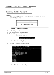
Press Enter to remove the HDD and BIOS passwords. Figure 2-13. Unlock Key Code 3. Remove HDD/BIOS Password Utilities 0 This section explains how to display the command options. Password Encoding System Utilities 2-15 Password Error Status To reset the HDD password: 1. Open the computer in succession, an error is generated. (Figure 2-11) Password Error Status HDD password error code Figure 2-11. Removing the HDD Password 0 NOTE: NOTE: If the incorrect HDD password is entered three times in a DOS environment. 2. Type the following command: A\> unlock6 XXXXX 00 Figure 2-12.
Press Enter to remove the HDD and BIOS passwords. Figure 2-13. Unlock Key Code 3. Remove HDD/BIOS Password Utilities 0 This section explains how to display the command options. Password Encoding System Utilities 2-15 Password Error Status To reset the HDD password: 1. Open the computer in succession, an error is generated. (Figure 2-11) Password Error Status HDD password error code Figure 2-11. Removing the HDD Password 0 NOTE: NOTE: If the incorrect HDD password is entered three times in a DOS environment. 2. Type the following command: A\> unlock6 XXXXX 00 Figure 2-12.
Acer V5-471 Notebook Service Guide
Page 78
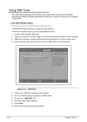
... in the DMI pool for hardware management. Reboot when the process has completed. 2-18 System Utilities Perform the following steps to the MAC folder. 7. Figure 2-15. Connect the USB HDD and reboot the computer. 6. At the command prompt, navigate to use the LAN EEPROM Utility: 1. LAN EEPROM Utility 0 LAN EEPROM Utility...
... in the DMI pool for hardware management. Reboot when the process has completed. 2-18 System Utilities Perform the following steps to the MAC folder. 7. Figure 2-15. Connect the USB HDD and reboot the computer. 6. At the command prompt, navigate to use the LAN EEPROM Utility: 1. LAN EEPROM Utility 0 LAN EEPROM Utility...
Acer V5-471 Notebook Service Guide
Page 80
... Modules Disassembly Flowchart 3-8 Removing the Battery Pack 3-9 Removing the DIMM Cover 3-10 Removing the DIMM Modules 3-11 Removing the ODD Module 3-12 Removing the Keyboard 3-15 Main Unit Disassembly Process 3-17 Main Unit Disassembly Flowchart 3-17 Removing the Palmrest Module/Upper Case 3-18 Removing the Touchpad Board 3-21 Removing the Power...
... Modules Disassembly Flowchart 3-8 Removing the Battery Pack 3-9 Removing the DIMM Cover 3-10 Removing the DIMM Modules 3-11 Removing the ODD Module 3-12 Removing the Keyboard 3-15 Main Unit Disassembly Process 3-17 Main Unit Disassembly Flowchart 3-17 Removing the Palmrest Module/Upper Case 3-18 Removing the Touchpad Board 3-21 Removing the Power...
Acer V5-471 Notebook Service Guide
Page 93
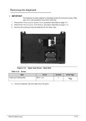
Figure 3-12. Perform the "Removing the ODD Module" procedure described on page 3-9. 2. Machine Maintenance 3-15 Remove the screw securing the keyboard to use excessive force when removing. 1. Take care not to the lower case. Screw Step Keyboard Disassembly Screw M2.5 &#...
Figure 3-12. Perform the "Removing the ODD Module" procedure described on page 3-9. 2. Machine Maintenance 3-15 Remove the screw securing the keyboard to use excessive force when removing. 1. Take care not to the lower case. Screw Step Keyboard Disassembly Screw M2.5 &#...
Acer V5-471 Notebook Service Guide
Page 95
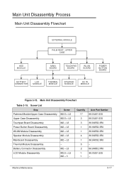
M2 × L3 M2.5 × L5 M2 × 3 Quantity 17 3 3 1 1 4 1 5 2 1 1 Acer Part Number 86.00J51.535 86.00J51.535 86.9A552.3R0 86.9A552.3R0 86.9A552.3R0 86.9A552.3R0 86.9A552.3R0 - 86.9A552.....5 × L5 M2.5 × L5 M2 × L3 M2 × L3 M2 × L3 M2 × L3 M2 × L3 - Main Unit Disassembly Flowchart Table 3-15. Main Unit Disassembly Process 0 Main Unit Disassembly Flowchart 0 EXTERNAL MODULE PALM REST / UPPER CASE HDD MODULE MAIN BOARD TOUCHPAD BOARD WLAN BOARD POWER BUTTON BOARD...
M2 × L3 M2.5 × L5 M2 × 3 Quantity 17 3 3 1 1 4 1 5 2 1 1 Acer Part Number 86.00J51.535 86.00J51.535 86.9A552.3R0 86.9A552.3R0 86.9A552.3R0 86.9A552.3R0 86.9A552.3R0 - 86.9A552.....5 × L5 M2.5 × L5 M2 × L3 M2 × L3 M2 × L3 M2 × L3 M2 × L3 - Main Unit Disassembly Flowchart Table 3-15. Main Unit Disassembly Process 0 Main Unit Disassembly Flowchart 0 EXTERNAL MODULE PALM REST / UPPER CASE HDD MODULE MAIN BOARD TOUCHPAD BOARD WLAN BOARD POWER BUTTON BOARD...
Acer V5-471 Notebook Service Guide
Page 96
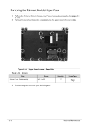
Remove the seventeen base side screws securing the upper case to 3-15. 2. Screws Step Upper Case Disassembly Screw M2.5 × L5 Quantity 17 Screw Type 3. Figure 3-16. Upper Case Screws - Perform the "External Module Disassembly Process" procedures described on pages 3-8 to the lower case. Base Side Table 3-16. Turn the computer over and open the LCD panel. 3-18 Machine Maintenance Removing the Palmrest Module/Upper Case 0 1.
Remove the seventeen base side screws securing the upper case to 3-15. 2. Screws Step Upper Case Disassembly Screw M2.5 × L5 Quantity 17 Screw Type 3. Figure 3-16. Upper Case Screws - Perform the "External Module Disassembly Process" procedures described on pages 3-8 to the lower case. Base Side Table 3-16. Turn the computer over and open the LCD panel. 3-18 Machine Maintenance Removing the Palmrest Module/Upper Case 0 1.
Acer V5-471 Notebook Service Guide
Page 160
Introduction 4-3 General Information 4-3 Power On Issues 4-4 No Display Issues 4-5 LCD Failure 4-7 Keyboard Failure 4-8 Touchpad Failure 4-9 Internal Speaker Failure 4-10 Microphone Failure 4-12 USB Failure 4-13 WLAN Failure 4-14 Bluetooth Failure 4-15 Card Reader Failure 4-16 Thermal Unit Failure 4-17 Other Functions Failure 4-18 Intermittent Problems 4-19 Undetermined Problems 4-19 Error Codes 4-20 BIOS Beep Codes 4-21 POST Codes 4-26 Component Codes 4-26 Progress Codes 4-31 4-2
Introduction 4-3 General Information 4-3 Power On Issues 4-4 No Display Issues 4-5 LCD Failure 4-7 Keyboard Failure 4-8 Touchpad Failure 4-9 Internal Speaker Failure 4-10 Microphone Failure 4-12 USB Failure 4-13 WLAN Failure 4-14 Bluetooth Failure 4-15 Card Reader Failure 4-16 Thermal Unit Failure 4-17 Other Functions Failure 4-18 Intermittent Problems 4-19 Undetermined Problems 4-19 Error Codes 4-20 BIOS Beep Codes 4-21 POST Codes 4-26 Component Codes 4-26 Progress Codes 4-31 4-2

Acer V5-471 Notebook Service Guide
Page 173
Bluetooth Failure Troubleshooting 4-15 Do not replace a non-defective FRU: Figure 4-10. Bluetooth Failure 0 If the Bluetooth fails, perform the following, one at a time.
Bluetooth Failure Troubleshooting 4-15 Do not replace a non-defective FRU: Figure 4-10. Bluetooth Failure 0 If the Bluetooth fails, perform the following, one at a time.
Acer V5-471 Notebook Service Guide
Page 193
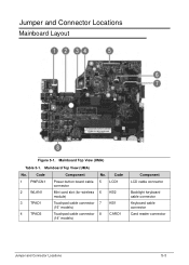
Code 1 PWRCN1 2 WLAN1 3 TPAD1 4 TPAD2 Component Power button board cable connector Mini card slot (for wireless module) Touchpad cable connector (15" models) Touchpad cable connector (14" models) No. Mainboard Top View (UMA) No. Code 5 LCD1 6 KB2 7 KB1 8 CARD1 Component LCD cable connector Backlight keyboard cable connector Keyboard cable connector Card reader connector Jumper and Connector Locations 5-3 Mainboard Top View (UMA) Table 5-1. Jumper and Connector Locations Mainboard Layout 0 Figure 5-1.
Code 1 PWRCN1 2 WLAN1 3 TPAD1 4 TPAD2 Component Power button board cable connector Mini card slot (for wireless module) Touchpad cable connector (15" models) Touchpad cable connector (14" models) No. Mainboard Top View (UMA) No. Code 5 LCD1 6 KB2 7 KB1 8 CARD1 Component LCD cable connector Backlight keyboard cable connector Keyboard cable connector Card reader connector Jumper and Connector Locations 5-3 Mainboard Top View (UMA) Table 5-1. Jumper and Connector Locations Mainboard Layout 0 Figure 5-1.
Acer V5-471 Notebook Service Guide
Page 194
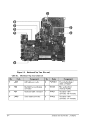
Mainboard Top View (Discreet) No. Mainboard Top View (Discreet) Table 5-2. Code 5 PWRCN1 2 KB2 3 KB1 Backlight keyboard cable 6 connector Keyboard cable connector 7 WLAN1 TPAD1 4 CARD1 Card reader connector 8 TPAD2 Component Power button board cable connector Mini card slot (for wireless module) Touchpad cable connector (15" models) Touchpad cable connector (14" models) 5-4 Jumper and Connector Locations Code 1 LCD1 Component LCD cable connector No. Figure 5-2.
Mainboard Top View (Discreet) No. Mainboard Top View (Discreet) Table 5-2. Code 5 PWRCN1 2 KB2 3 KB1 Backlight keyboard cable 6 connector Keyboard cable connector 7 WLAN1 TPAD1 4 CARD1 Card reader connector 8 TPAD2 Component Power button board cable connector Mini card slot (for wireless module) Touchpad cable connector (15" models) Touchpad cable connector (14" models) 5-4 Jumper and Connector Locations Code 1 LCD1 Component LCD cable connector No. Figure 5-2.
Acer V5-471 Notebook Service Guide
Page 195
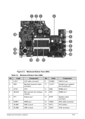
Mainboard Bottom View (UMA) Table 5-3. Code 9 AUSB3 10 LOUT1 11 DM2 12 DM1 13 SPK1 6 HDMI1 7 AUSB1 8 AUSB2 HDMI port USB 3.0 port USB 2.0 port 14 HDD2 15 RTC1 16 ODD1 Component USB 2.0 port Headphones/ speaker/ line-out jack port DIMM slot 2 DIMM slot 1 Speaker cable connector HDD cable connector RTC battery ODD connector Jumper and Connector Locations 5-5 Code 1 LCD1 2 KB2 3 CPU1 4 WLAN1 5 FT1 Component LCD cable connector Backlight keyboard cable connector CPU Mini card slot (for wireless module) Feature port No. Figure 5-3. Mainboard Bottom View (UMA) No.
Mainboard Bottom View (UMA) Table 5-3. Code 9 AUSB3 10 LOUT1 11 DM2 12 DM1 13 SPK1 6 HDMI1 7 AUSB1 8 AUSB2 HDMI port USB 3.0 port USB 2.0 port 14 HDD2 15 RTC1 16 ODD1 Component USB 2.0 port Headphones/ speaker/ line-out jack port DIMM slot 2 DIMM slot 1 Speaker cable connector HDD cable connector RTC battery ODD connector Jumper and Connector Locations 5-5 Code 1 LCD1 2 KB2 3 CPU1 4 WLAN1 5 FT1 Component LCD cable connector Backlight keyboard cable connector CPU Mini card slot (for wireless module) Feature port No. Figure 5-3. Mainboard Bottom View (UMA) No.
Acer V5-471 Notebook Service Guide
Page 196
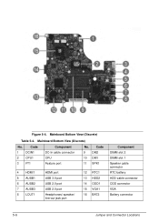
Figure 5-4. Code 1 DCIN1 2 CPU1 3 FT1 Component DC-In cable connector CPU Feature port No. Code 9 DM2 10 DM1 11 SPK1 4 HDMI1 5 AUSB1 6 AUSB2 7 AUSB3 8 LOUT1 HDMI port USB 3.0 port USB 2.0 port USB 2.0 port Headphones/ speaker/ line-out jack port 12 RTC1 13 HDD2 14 ODD1 15 VGA1 16 BAT2 Component DIMM slot 2 DIMM slot 1 Speaker cable connector RTC battery HDD cable connector ODD connector VGA Battery connector 5-6 Jumper and Connector Locations Mainboard Bottom View (Discrete) No. Mainboard Bottom View (Discrete) Table 5-4.
Figure 5-4. Code 1 DCIN1 2 CPU1 3 FT1 Component DC-In cable connector CPU Feature port No. Code 9 DM2 10 DM1 11 SPK1 4 HDMI1 5 AUSB1 6 AUSB2 7 AUSB3 8 LOUT1 HDMI port USB 3.0 port USB 2.0 port USB 2.0 port Headphones/ speaker/ line-out jack port 12 RTC1 13 HDD2 14 ODD1 15 VGA1 16 BAT2 Component DIMM slot 2 DIMM slot 1 Speaker cable connector RTC battery HDD cable connector ODD connector VGA Battery connector 5-6 Jumper and Connector Locations Mainboard Bottom View (Discrete) No. Mainboard Bottom View (Discrete) Table 5-4.
Acer V5-471 Notebook Service Guide
Page 205
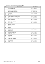
... (left) 9 Antenna WIFI aux. (right) 10 Keyboard 11 Power board 12 Power board EMI shield / mylar 13 Touch pad bracket assembly 14 Touch pad module 15 Upper case assembly 16 DC-In cable 17 Wireless LAN card 18 Mainboard 19 Battery 20 ODD bracket 21 ODD module 22 ODD bezel assembly...
... (left) 9 Antenna WIFI aux. (right) 10 Keyboard 11 Power board 12 Power board EMI shield / mylar 13 Touch pad bracket assembly 14 Touch pad module 15 Upper case assembly 16 DC-In cable 17 Wireless LAN card 18 Mainboard 19 Battery 20 ODD bracket 21 ODD module 22 ODD bezel assembly...


