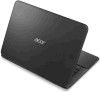
Acer S5-391 Notebook Service Guide
Page 2
Jumper and Connector Locations Mainboard Top View 3-2 Mainboard Bottom View 3-3 LED Board View 3-4 Audio Board View 3-5 Battery Board View 3-6 Card Reader Board View 3-7 Motor Board View 3-8 Clear CMOS Jumper 3-9 Chapter 4. Troubleshooting General Information 4-2 Power On Issues 4-3 No Display Issues 4-4 LCD Picture Failure 4-6 ...
Acer S5-391 Notebook Service Guide
Page 3
... Flowchart 5-4 Getting Started 5-6 SD Card Removal 5-7 SD Card Installation 5-8 Palm Rest Removal 5-9 Palm Rest Installation 5-11 Battery Module Removal 5-13 Battery Module Installation 5-14 Touchpad Module Removal 5-16 Touchpad Module Installation 5-17 Upper Case Removal 5-19 Upper Case Installation 5-24 Touchpad... FFC Removal 5-28 Touchpad FFC Installation 5-29 Battery Board Removal 5-30 Battery Board Installation 5-33 LED Board Removal 5-36 LED Board Installation 5-37 Audio Board Removal 5-38 Audio Board ...
Acer S5-391 Notebook Service Guide
Page 11
...) Weight • 1.2 kg (2.646 lbs.) with 4-cell battery pack Power Adapter and Battery • ACPI 3.0 CPU power management standard: supports Standby and Hibernation power-saving modes Battery • • • 35.5W 2400mAh 4-cell Li-Polymer battery pack Battery life: 6.5 hours ENERGY STAR® Power Adapter • ...HDMI® port with HDCP support • One Headphone/speaker jack, supporting 3.5 mm headset with built-in microphone for iPhone or Acer smart phone • One Lanyard • DC-in jack for AC adapter Special Keys and Controls Control Buttons • Power ...
Acer S5-391 Notebook Service Guide
Page 13
... status: • Off: System is off. • Blue: System is on. • Amber (flashing): S3 state Indicates the computer battery status: • Amber (flashing): Battery low. • Amber: Battery is charging. • Blue: Battery is fully charged. Receives audio input for video communications. Hardware Specifications and Configurations 1-6 Use to enter data into the computer...
Acer S5-391 Notebook Service Guide
Page 23
...-ON BOARD Figure 1-9. LS-8482P Card Reader/B DC/DC Interface CKT. LS-8483P LED/B EC ROM x1 @ for KB930 Power Circuit DC/DC LS-8484P Battery/B 1-16 DMIC x 1 Phone Jack x 1 mSATA LPC BUS 33MHz ENE KB930/KB9012 RTC CKT.
Acer S5-391 Notebook Service Guide
Page 24
... 12.77 in Width 227.3 mm 8.95 in Height (front to rear) 14.98 mm 0.59 in Weight (equipped with optical drive, flash drive, and battery) 1.2 kg 2.646 lbs Input power Operating voltage 19V Operating current 3.42A Temperature Operating 0ºC ~ 40ºC 32ºF ~ 104ºF Non-operating -20ºC ~ 60...
Acer S5-391 Notebook Service Guide
Page 32
... Pack capacity Number of battery cell Package configuration SANYO AP12B Li-Polymer 2400 mAh 4 4S1P Specification USB Port Item USB compliance level Protocol Number of USB port(s) Location Output Current ...
Acer S5-391 Notebook Service Guide
Page 33
... completely. System saves all system states and data onto the disc prior to Disk (S4) Also called Hibernation Mode. Battery abnormal stop charge or batter in this state. Soft Off (G2/S5) OS initiated shutdown. Suspend to RAM (S3) • CPU Set Power Down • VGA Suspend • ..., SD) • Non-push-push No logo on dummy card System LED Indicator Item Lock System state HDD access state Wireless state Power button backlight Battery state Specification N/A • Blue color solid on: System on • Blue color and amber color off: System off • Amber color blinking: S3 ...
Acer S5-391 Notebook Service Guide
Page 48
... used . Prepare a bootable USB HDD/FDD. 2. BIOS Flash Utilities BIOS Flash memory updates are required for the following to run a BIOS Flash update: 1. If the battery pack does not contain power to the bootable USB HDD/FDD. Use the Flash utility to update the system BIOS Flash ROM. BIOS Flash may...
Acer S5-391 Notebook Service Guide
Page 53
... is low, the following message is shown: Figure 2-23. BIOS ROM File Size Error Message System Utilities 2-17 Battery Power Warning Message • Check the BIOS ROM file size. If the BIOS ROM file size is different from the ROM part size, the following ...
Acer S5-391 Notebook Service Guide
Page 58
Figure 2-28. Unplug the AC Adapter 2. Figure 2-29. Remove the battery (see Battery Module Removal on page 5-13). Remove the Battery 2-22 System Utilities Unplug the AC adapter. Clearing the Password Check and BIOS Password Clearing the Password Check To remove the password check, perform the following: 1.
Acer S5-391 Notebook Service Guide
Page 59
Disconnect the Motor Board Cable 4. Connect the Motor Board Cable 5. Plug the AC adapter. Figure 2-31. 3. System Utilities 2-23 Install the battery (see Battery Module Installation on page 5-14). 7. Connect the motor board cable connector (JP1). Connect the motor board cable connector (JP1). 6. Disconnect the motor board cable connector (JP1). Figure 2-30.
Acer S5-391 Notebook Service Guide
Page 66
CHAPTER 3 Jumper and Connectors Location Jumper and Connector Locations 3-2 Mainboard Top View 3-2 Mainboard Bottom View 3-3 LED Board View 3-4 Audio Board View 3-5 Battery Board View 3-6 Card Reader Board View 3-7 Motor Board View 3-8 Clear CMOS Jumper 3-9
Acer S5-391 Notebook Service Guide
Page 67
Mainboard Top Jumper and Connectors Description Item Description Thunderbolt Connector JTP1 Connect to Touchpad USB 3.0 Connector JKB1 Connect to Keyboard USB 3.0 Connector PJP2 Connect to Battery/B HDMI Connector JAUDIO Connect to Audio/B Connect to LED/B JMINI1 Connect to SSD Module Connect to Panel and Card Reader/B JMR1 Connect to Motor/B Connect ...
Acer S5-391 Notebook Service Guide
Page 69
LED Board Jumper Description Power State Indicator Battery Charging Indicator Jumper and Connector Locations 3-4 LED Board View LED1 LED2 LED1 LED2 Item Figure 3-3. LED Board Jumper Table 3-3.
Acer S5-391 Notebook Service Guide
Page 70
Audio Board Jumper Description Door status LED Motor open/close button Audio combo jack Battery reset button On-board MIC Connect to M/B Connect to speaker Jumper and Connector Locations 3-5 Audio Board Jumper Table 3-4. Audio Board View SW1 Top View LED1 JHP1 SW2 MIC1 Bottom View JAUDIO JSPK1 LED1 SW1 JHP1 SW2 MIC1 JAUDIO JSPK1 Item Figure 3-4.
Acer S5-391 Notebook Service Guide
Page 71
Battery Board Jumper Item Description JP2 Connect to Battery JP3 Connect to Battery JP1 Connect to M/B Jumper and Connector Locations 3-6 Battery Board View JP2 JP3 JP1 Figure 3-5. Battery Board Jumper Table 3-5.
Acer S5-391 Notebook Service Guide
Page 73
Motor Board Jumper Table 3-7. Motor Board Jumper Description Connect to Right VR/B Connect to Right motor RTC Battery Connect to Left VR/B Connect to M/B Connect to Left motor Jumper and Connector Locations 3-8 Motor Board View PBJ1 JVR2 JMT2 JVR2 JMT2 PBJ1 JVR1 JP1 JMT1 Item JVR1 JP1 JMT1 Figure 3-7.
Acer S5-391 Notebook Service Guide
Page 77
... Unit Thermal Failure on page 4-26) and fan airways are not necessary to boot the computer to Online Support Information on NG OK Swap AC/Battery Check Power/B NG Whether OK OK Swap Power SW/B Check LCD cable Whether OK OK Swap M/B NG Swap LCD cable Figure 4-1. Power On Issues Computer...
Acer S5-391 Notebook Service Guide
Page 79
... the Windows Memory Diagnostic from the operating system DVD and follow the on page 8-2. 4-5 Troubleshooting Adjust the brightness to the User Manual for instructions on battery alone as this may reduce display brightness. 2. Boot the computer. • If permanent vertical/horizontal lines or dark spots appear in the same location, the...