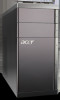
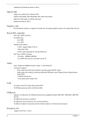
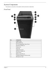
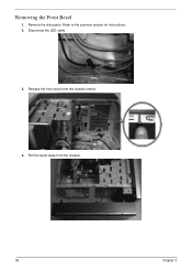
Acer Aspire M5811 Front Panel
Related Manual Pages

Similar Questions

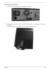
How To Remove The Side Panel From Acer Aspire 3800?
My Acer Aspire 3800 is dusty inside and I wish to clean it. The perforated side panel seems to be th...
My Acer Aspire 3800 is dusty inside and I wish to clean it. The perforated side panel seems to be th...
(Posted by Crumbs 7 years ago)

Front Panel Conection For An Acer G43t-am V2.0, Motherboard
I have replaced my front panel and disconnected the plugs now i can't remember which order they go b...
I have replaced my front panel and disconnected the plugs now i can't remember which order they go b...
(Posted by johnmallyb 11 years ago)

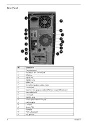
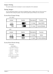
Front Panel
HOW TO iDENTIFY THE FRONT PANEL CONNECTIONS, AS i AM FITTING THIS BOARD INTO ANOTHER CASE i NEED TO ...
HOW TO iDENTIFY THE FRONT PANEL CONNECTIONS, AS i AM FITTING THIS BOARD INTO ANOTHER CASE i NEED TO ...
(Posted by brian17432 11 years ago)