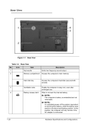
Acer Aspire 8951G Notebook Service Guide
Page 7
... MAC EEPROM Utility 2-28 CHAPTER 3 Maintenance Procedures Introduction 3-5 General Information 3-5 Recommended Equipment 3-5 Screw Table 3-5 Maintenance Flowchart 3-6 Getting Started 3-7 Dummy Card Removal 3-8 Dummy Card Installation 3-8 Logic Door Removal 3-9 Logic Door Installation 3-9 Battery Cable Removal 3-11 Battery Cable Installation 3-11 Lower Cover DIMM Module Removal 3-12 Lower Cover DIMM Module Installation 3-12 Main HDD (Hard Disk Drive) Module...
Acer Aspire 8951G Notebook Service Guide
Page 8
... Mainboard Installation 3-48 PCH Heatsink Removal 3-49 PCH Heatsink Installation 3-49 RTC Battery Removal 3-50 RTC Battery Installation 3-50 Thermal Assembly Removal 3-51 Thermal Assembly Installation 3-52 CPU Removal 3-53 CPU Installation 3-53 LCD (Liquid Crystal Display) Module Removal 3-55 LCD Module Installation 3-55 Speaker Module Removal 3-56 Speaker Module Installation 3-57 Battery Removal 3-58 Battery Installation 3-58 DC-IN Cable...
Acer Aspire 8951G Notebook Service Guide
Page 30
... computer to stay cool, even after prolonged use. 4 Battery release latch Slide to the disconnect battery position. In this position, the computer will only function if the AC adapter is embedded and not removable. Base View No Icon Item Description 1 Sub woofer Emits... low frequency sound output. 2 Memory compartment Houses the computer's main memory. NOTE: The computer's battery is connected. 1-20 Hardware Specifications and Configurations Base...
Acer Aspire 8951G Notebook Service Guide
Page 94
... 3-5 Maintenance Flowchart 3-6 Getting Started 3-7 Dummy Card Removal 3-8 Dummy Card Installation 3-8 Logic Door Removal 3-9 Logic Door Installation 3-9 Battery Cable Removal 3-11 Battery Cable Installation 3-11 Lower Cover DIMM Module Removal 3-12 Lower Cover DIMM Module Installation 3-12 Main HDD (Hard Disk Drive) Module Removal 3-13 HDD Module Installation 3-13 HDD Brackets Removal 3-14 HDD Brackets Installation 3-14 WLAN Module...
Acer Aspire 8951G Notebook Service Guide
Page 95
PCH Heatsink Removal 3-49 PCH Heatsink Installation 3-49 RTC Battery Removal 3-50 RTC Battery Installation 3-50 Thermal Assembly Removal 3-51 Thermal Assembly Installation 3-52 CPU Removal 3-53 CPU Installation 3-53 LCD (Liquid Crystal Display) Module Removal 3-55 LCD Module Installation 3-55 Speaker Module Removal 3-56 Speaker Module Installation 3-57 Battery Removal 3-58 Battery Installation 3-58 DC-IN Cable Removal 3-59 DC-IN Cable Installation 3-59 3-3
Acer Aspire 8951G Notebook Service Guide
Page 99
Place system on logic door to any maintenance procedures: 1. Battery Disconnect Switch Machine Maintenance Procedures 3-7 Observe the order of the hardware components. Move battery disconnect switch (B) on a stable work surface. 4. Perform the following prior to performing any of the sequence to avoid damage to remove power. (Figure 3-3) B Figure 3-3. Getting Started 0 The flowchart (Figure 3-1) identifies...
Acer Aspire 8951G Notebook Service Guide
Page 103
Battery Cable Removal 0 Prerequisite: Logic Door Removal 1. Install logic door. Disconnect battery cable (A) from mainboard connector (F). Connect battery cable (A) to mainboard connector (F). (Figure 3-7) 2. Machine Maintenance Procedures 3-11 Lower Cover Overview 2. Battery Cable Installation 0 1. Locate battery cable (A) on mainboard. (Figure 3-7) FA B E C D Figure 3-7.
Acer Aspire 8951G Notebook Service Guide
Page 104
... DIMM module (B). 4. Disconnect DIMM module (B) from mainboard connector (D). 4. Push down on lower cover. (Figure 3-7) 2. Repeat steps 2 and 3 for remaining DIMM module (C). Lower Cover DIMM Module Removal 0 Prerequisite: Battery Cable Removal 1.
Acer Aspire 8951G Notebook Service Guide
Page 105
... (A) to HDD module connector. (Figure 3-9) 2. Lifting Main HDD Module 3. Repeat Steps 1 through 4 for Secondary HDD Module as required. Main HDD (Hard Disk Drive) Module Removal 0 Prerequisite: Battery Cable Removal 1. Connect HDD cable (B) to lift HDD module until HDD cable clears lower cover. (Figure 3-9) A A B Figure 3-9. Install HDD module into bay on lower cover. (Figure...
Acer Aspire 8951G Notebook Service Guide
Page 107
Locate WLAN (Wireless Local Area Network) module (E) on WLAN module connectors (D). 4. Install and secure screw (C) to mainboard connector (D). (Figure 3-11) 2. Install logic door. WLAN Module Removal 0 Prerequisite: Battery Cable Removal 1. Connect main (A) and auxiliary (B) antenna cables on mainboard. (Figure 3-7) 2. Disconnect WLAN main (A) and auxiliary (B) antenna cables from mainboard connector (D). Disconnect WLAN module (E) from WLAN...
Acer Aspire 8951G Notebook Service Guide
Page 108
Locate touchpad removal switch (A). (Figure 3-12) A Figure 3-12. Move and hold switch as shown in Figure 3-13. Remove touchpad. 3-16 Machine Maintenance Procedures Touchpad Removal 0 Prerequisite: Battery Cable Removal 1. Touchpad Removal Switch 2. Figure 3-13. Removing Touchpad 3.
Acer Aspire 8951G Notebook Service Guide
Page 142
Remove RTC battery from RTC battery holder (B). + IMPORTANT: Follow local regulations for battery disposal. RTC Battery Installation 0 1. Install RTC battery (A) to RTC battery holder (B). (Figure 3-54) 2. RTC Battery Removal. 2. Install lower cover. 3-50 Machine Maintenance Procedures Locate RTC battery (A) on mainboard. (Figure 3-54) A B Figure 3-54. RTC Battery Removal 0 Prerequisite: Mainboard Removal 1.
Acer Aspire 8951G Notebook Service Guide
Page 150
Locate battery cable (A) in lower cover. (Figure 3-62) C B A Figure 3-62. Push battery cable through lower cover slot (B). 3. Install battery (C) on lower cover. (Figure 3-62) 2. Remove battery (C) from lower cover. Battery Installation 0 1. Push battery cable (A) through lower cover slot (B). 3. Install speaker module. 3-58 Machine Maintenance Procedures Battery Removal 0 Prerequisite: Speaker Module Removal 1. Battery Cable 2.
Acer Aspire 8951G Notebook Service Guide
Page 157
Make sure the computer has power by removing the power cable and battery. Connect an external monitor to the computer and switch between internal and external by pressing Fn+F5. 6. Disconnect power and all external devices including port ...
Acer Aspire 8951G Notebook Service Guide
Page 158
... faulty and should be replaced. Refer to Maintenance Flowchart. If the Issue is still not resolved, refer to Maintenance Flowchart). 11. Remove the drives (refer to Online Support Information. 8. Boot the computer. If permanent vertical/horizontal lines or dark spots appear... LCD is properly installed. Check the Device Manager to the User Manual for instructions on battery alone as this may reduce display brightness. 2. Refer to determine that the computer is discovered. 9. Remove any memory cards and CD/DVD discs. 8. Abnormal Video 0 If the video appears ...
Acer Aspire 8951G Notebook Service Guide
Page 172
... Step 8 and select an earlier time and date. 10. External Mouse Failure 0 If an external Mouse fails, perform the following: 1. Remove recently added software and reboot the computer. 8. If the mouse uses a USB connection, use a different USB port. 4. Restart the computer... and Support. 11. For more information refer to check the events log for errors. If the mouse uses a wireless connection, insert new batteries and confirm there is listed under Other Devices 14. Reinstall the program experiencing mouse failure. 5. Check the Device Manager to the mouse user manual...
Acer Aspire 8951G Notebook Service Guide
Page 173
... a time. Remove or disconnect all attached devices are found . 7. Apply power to Power On Issues). 1. When analyzing an intermittent problem, perform the following devices: Non-Acer devices Printer, mouse, and other external devices Battery pack ... there are incorrect, whether a short circuit is suspected, or whether the system is inoperative. Remove power from the computer. 2. If the problem does not recur, connect the removed devices one at the time of reasons that have nothing to verify that all of the following...
Acer Aspire 8951G Notebook Service Guide
Page 191
... Started. 5. Refer to initiate system CRISIS mode. 8. Jumper and Connector Locations 5-9 Copy ROM (read-only memory) file, ZRH.fd, to root directory of USB HDD. Remove battery power and AC power adapter. Update the latest BIOS version for this machine by the regular BIOS flashing process. Make sure that there is no...