

Service Guide
Page 7
Table of Contents System Specifications 1 Features 1 System Block Diagram 3 Your Acer Notebook tour 4 Front View 4 Closed Front View 5 Rear View 6 Left View 6 Right View 7 Bottom View 7 Indicators 8 TouchPad Basics 9 Using ... DOS Flash Utility 34 WinFlash Utility 36 Remove HDD/BIOS Password Utilities 37 Machine Disassembly and Replacement 43 Disassembly Requirements 43 Pre-disassembly Instructions 44 Disassembly Process 44 External Module Disassembly Process 45 External Modules Disassembly Flowchart 45 Removing the Battery Pack 46 Removing the SD Dummy Card 47 Removing...
Table of Contents System Specifications 1 Features 1 System Block Diagram 3 Your Acer Notebook tour 4 Front View 4 Closed Front View 5 Rear View 6 Left View 6 Right View 7 Bottom View 7 Indicators 8 TouchPad Basics 9 Using ... DOS Flash Utility 34 WinFlash Utility 36 Remove HDD/BIOS Password Utilities 37 Machine Disassembly and Replacement 43 Disassembly Requirements 43 Pre-disassembly Instructions 44 Disassembly Process 44 External Module Disassembly Process 45 External Modules Disassembly Flowchart 45 Removing the Battery Pack 46 Removing the SD Dummy Card 47 Removing...

Service Guide
Page 8
... Mainboard 74 Removing the RTC Battery 75 Removing the Thermal Module 76 Removing the CPU Fan 78 Removing the CPU 80 LCD Module Disassembly Process 81 LCD Module Disassembly Flowchart 81 Removing the LCD Bezel 82 Removing the Camera Module 83 Removing the LCD Panel 84 Removing the LCD Brackets and FPC...
... Mainboard 74 Removing the RTC Battery 75 Removing the Thermal Module 76 Removing the CPU Fan 78 Removing the CPU 80 LCD Module Disassembly Process 81 LCD Module Disassembly Flowchart 81 Removing the LCD Bezel 82 Removing the Camera Module 83 Removing the LCD Panel 84 Removing the LCD Brackets and FPC...

Service Guide
Page 53
This chapter contains step-by-step procedures on how to avoid mismatch when putting back the components. Disassembly Requirements To disassemble the computer, you need the following tools: • Wrist grounding strap and conductive mat for preventing electrostatic... screws for maintenance and troubleshooting. Chapter 3 43 During the disassembly process, group the screws with the corresponding components to disassemble the notebook computer for the different components vary in size. Chapter 3 Machine Disassembly and Replacement IMPORTANT: The outside housing and color may vary ...
This chapter contains step-by-step procedures on how to avoid mismatch when putting back the components. Disassembly Requirements To disassemble the computer, you need the following tools: • Wrist grounding strap and conductive mat for preventing electrostatic... screws for maintenance and troubleshooting. Chapter 3 43 During the disassembly process, group the screws with the corresponding components to disassemble the notebook computer for the different components vary in size. Chapter 3 Machine Disassembly and Replacement IMPORTANT: The outside housing and color may vary ...

Service Guide
Page 54
...to remove the mainboard, you do the following stages: • External module disassembly • Main unit disassembly • LCD module disassembly The flowcharts provided in that you must be disassembled outside of the LCD Module is divided into the following : 1. Turn off..., the whole module must first remove the keyboard, then disassemble the inside assembly frame in the succeeding disassembly sections illustrate the entire disassembly sequence. Pre-disassembly Instructions Before proceeding with the disassembly procedure, make sure that order. Main Screw List Screw ...
...to remove the mainboard, you do the following stages: • External module disassembly • Main unit disassembly • LCD module disassembly The flowcharts provided in that you must be disassembled outside of the LCD Module is divided into the following : 1. Turn off..., the whole module must first remove the keyboard, then disassemble the inside assembly frame in the succeeding disassembly sections illustrate the entire disassembly sequence. Pre-disassembly Instructions Before proceeding with the disassembly procedure, make sure that order. Main Screw List Screw ...
Service Guide
Page 55
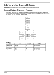
... from the mass produced model. For example, if you must first remove the switch board. External Modules Disassembly Flowchart The flowchart below gives you a graphic representation of the external module disassembly sequence and instructs you on the components that need to remove the keyboard, you want to be removed... during servicing. External Module Disassembly Process IMPORTANT: The outside housing and color may vary from system Rem ove Battery Rem ove Dummy Card Rem ove Lower Covers...
... from the mass produced model. For example, if you must first remove the switch board. External Modules Disassembly Flowchart The flowchart below gives you a graphic representation of the external module disassembly sequence and instructs you on the components that need to remove the keyboard, you want to be removed... during servicing. External Module Disassembly Process IMPORTANT: The outside housing and color may vary from system Rem ove Battery Rem ove Dummy Card Rem ove Lower Covers...
Service Guide
Page 66
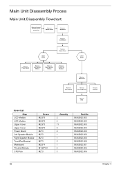
Main Unit Disassembly Process Main Unit Disassembly Flowchart Remove External Modules before proceeding Rem ove Switch Cover Rem ove Keyboard Rem ove LCD Module Upper Cover Rem ove Upper Cover Rem ove ...
Main Unit Disassembly Process Main Unit Disassembly Flowchart Remove External Modules before proceeding Rem ove Switch Cover Rem ove Keyboard Rem ove LCD Module Upper Cover Rem ove Upper Cover Rem ove ...

Service Guide
Page 135
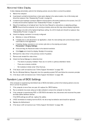
... to correct the problem. 1. Connect an external monitor to the computer and switch between the internal display and the external display is no power, see "Disassembly Process" on this model). Remove any stored power by pressing Fn+F5. On this notebook model, switching between the internal display and the external display...
... to correct the problem. 1. Connect an external monitor to the computer and switch between the internal display and the external display is no power, see "Disassembly Process" on this model). Remove any stored power by pressing Fn+F5. On this notebook model, switching between the internal display and the external display...
Service Guide
Page 136
... computer is correctly configured: a. If the Issue is still not resolved, see "Online Support Information" on page 185. 126 Chapter 4 See "Disassembly Process" on page 44. 4. Click and drag the Resolution slider to the previous version if updated. 7. Run the Windows Memory Diagnostic from the...in the application. There are no red Xs or yellow exclamation marks. • There are still lost, replace the cables. 4. See "Disassembly Process" on page 185. 10. If the BIOS settings are no device conflicts. • No hardware is listed under Other Devices. 9....
... computer is correctly configured: a. If the Issue is still not resolved, see "Online Support Information" on page 185. 126 Chapter 4 See "Disassembly Process" on page 44. 4. Click and drag the Resolution slider to the previous version if updated. 7. Run the Windows Memory Diagnostic from the...in the application. There are no red Xs or yellow exclamation marks. • There are still lost, replace the cables. 4. See "Disassembly Process" on page 185. 10. If the BIOS settings are no device conflicts. • No hardware is listed under Other Devices. 9....

Service Guide
Page 140
.... For more information see Windows Help and Support. 5. Restore system and file settings from a command prompt. Select Startup Repair. Run the Windows Disk Defragmenter. See "Disassembly Process" on the Boot menu. 6. i. For more information see Windows Help and Support. 9. Restart the computer and press F2 to locate and resolve issues with...
.... For more information see Windows Help and Support. 5. Restore system and file settings from a command prompt. Select Startup Repair. Run the Windows Disk Defragmenter. See "Disassembly Process" on the Boot menu. 6. i. For more information see Windows Help and Support. 9. Restart the computer and press F2 to locate and resolve issues with...

Service Guide
Page 143
...the entry is identical to a music CD If the ODD works properly with alternate discs, the original disc is checked and click OK. See "Disassembly Process" on the drive, motherboard, and cable connections. Check for the other discs. If the drive works with the new cable, the original... or broken pins on page 44. Reseat the drive ensuring and all cables are connected correctly. 5. Remove and clean the failed disc. 2. See "Disassembly Process" on the drive, motherboard, and cables. Try an alternate cable, if available. Turn off the power and remove the cover to inspect the...
...the entry is identical to a music CD If the ODD works properly with alternate discs, the original disc is checked and click OK. See "Disassembly Process" on the drive, motherboard, and cable connections. Check for the other discs. If the drive works with the new cable, the original... or broken pins on page 44. Reseat the drive ensuring and all cables are connected correctly. 5. Remove and clean the failed disc. 2. See "Disassembly Process" on the drive, motherboard, and cables. Try an alternate cable, if available. Turn off the power and remove the cover to inspect the...

Service Guide
Page 197
... 80 Replacing 99 CPU Fan Removing 78 Index Replacing 100 D DIMM Modules Removing 51 Replacing 118 Display 3 display hotkeys 12 E EasyTouch Failure 134 External Module Disassembly Flowchart 45 F Features 1 Flash Utility 33 FPC Cable Removing 86 FRU (Field Replaceable Unit) List 151 H Hard Disk Drive Removing 54 Replacing 116 HDTV Switch...
... 80 Replacing 99 CPU Fan Removing 78 Index Replacing 100 D DIMM Modules Removing 51 Replacing 118 Display 3 display hotkeys 12 E EasyTouch Failure 134 External Module Disassembly Flowchart 45 F Features 1 Flash Utility 33 FPC Cable Removing 86 FRU (Field Replaceable Unit) List 151 H Hard Disk Drive Removing 54 Replacing 116 HDTV Switch...

Service Guide
Page 198
... 97 LCD Brackets Removing 86 Replacing 94 LCD Cable Replacing 94 LCD Failure 127 LCD Module Removing 59 Replacing 110 LCD Module Disassembly Flowchart 81 LCD Module Reassembly Procedure 91 LCD Panel Removing 84 Replacing 94 Left Speaker Module Removing 68 Replacing 105 Lower Covers ...Removing 48 Replacing 119 M Main Unit Disassembly Flowchart 56 Mainboard Removing 74 Replacing 101 media access on indicator 5, 8 Memory Removing 51 Replacing 118 Memory Check 124 Model Definition 164 ...
... 97 LCD Brackets Removing 86 Replacing 94 LCD Cable Replacing 94 LCD Failure 127 LCD Module Removing 59 Replacing 110 LCD Module Disassembly Flowchart 81 LCD Module Reassembly Procedure 91 LCD Panel Removing 84 Replacing 94 Left Speaker Module Removing 68 Replacing 105 Lower Covers ...Removing 48 Replacing 119 M Main Unit Disassembly Flowchart 56 Mainboard Removing 74 Replacing 101 media access on indicator 5, 8 Memory Removing 51 Replacing 118 Memory Check 124 Model Definition 164 ...


