Quick Start Guide
Page 3
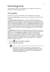
... the model you get started with language such as system utilities, data recovery, expansion options and troubleshooting. This guide contains detailed information on AcerSystem User Guide will occasionally refer to access it contains warranty information and the general regulations and safety notices for Starters... Note: Viewing the file requires Adobe Reader. Follow the instructions on the screen to use your Acer notebook, we have designed a set of...
... the model you get started with language such as system utilities, data recovery, expansion options and troubleshooting. This guide contains detailed information on AcerSystem User Guide will occasionally refer to access it contains warranty information and the general regulations and safety notices for Starters... Note: Viewing the file requires Adobe Reader. Follow the instructions on the screen to use your Acer notebook, we have designed a set of...

Quick Start Guide
Page 5
... right speakers deliver stereo audio output. 5 Keyboard For entering data into your hands when you use the computer. 9 HDD Indicates when the hard disk drive is active. Hotkeys The computer employs hotkeys or key combinations to save power. Press any key to return. Wireless LAN communication button/indicator Enables/disables the wireless LAN function. Hotkey Icon + + + Function Sleep Display toggle Screen blank Description Puts the computer in the hotkey combination. Num Lock Lights up when Caps Lock is activated. Power button Turns the computer on...
... right speakers deliver stereo audio output. 5 Keyboard For entering data into your hands when you use the computer. 9 HDD Indicates when the hard disk drive is active. Hotkeys The computer employs hotkeys or key combinations to save power. Press any key to return. Wireless LAN communication button/indicator Enables/disables the wireless LAN function. Hotkey Icon + + + Function Sleep Display toggle Screen blank Description Puts the computer in the hotkey combination. Num Lock Lights up when Caps Lock is activated. Power button Turns the computer on...

Quick Start Guide
Page 6
... the computer cover is charging. 2. English 6 Hotkey Icon + + < > + < > + < > + < > Function Description Speaker toggle Turns the speakers on and off. Volume up Increases the screen brightness. Volume down Decreases the screen brightness. Fully charged: The light shows blue when in AC mode. 2 Multi-in-1 Accepts Secure Digital (SD), MultiMediaCard card (MMC), Memory Stick (MS), Memory Stick PRO (MS reader PRO), xD-Picture Card (xD). Note: Push to remove/install the card. Brightness up Increases the sound volume. Closed front...
... the computer cover is charging. 2. English 6 Hotkey Icon + + < > + < > + < > + < > Function Description Speaker toggle Turns the speakers on and off. Volume up Increases the screen brightness. Volume down Decreases the screen brightness. Fully charged: The light shows blue when in AC mode. 2 Multi-in-1 Accepts Secure Digital (SD), MultiMediaCard card (MMC), Memory Stick (MS), Memory Stick PRO (MS reader PRO), xD-Picture Card (xD). Note: Push to remove/install the card. Brightness up Increases the sound volume. Closed front...
Quick Start Guide
Page 10
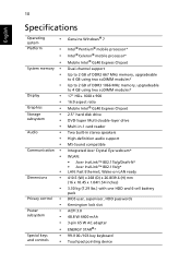
... MHz memory, upgradeable to 4 GB using two soDIMM modules* Up to 2 GB of DDR3 1066 MHz memory, upgradeable to 4 GB using two soDIMM modules* 17" HD+ 1600 x 900 16:9 aspect ratio Mobile Intel® GL40 Express Chipset 2.5" hard disk drive DVD-Super Multi double-layer drive Multi-in-1 card reader Two built-in stereo speakers High-definition audio support MS-Sound compatible Integrated Acer Crystal Eye webcam* WLAN: • Acer InviLink...
... MHz memory, upgradeable to 4 GB using two soDIMM modules* Up to 2 GB of DDR3 1066 MHz memory, upgradeable to 4 GB using two soDIMM modules* 17" HD+ 1600 x 900 16:9 aspect ratio Mobile Intel® GL40 Express Chipset 2.5" hard disk drive DVD-Super Multi double-layer drive Multi-in-1 card reader Two built-in stereo speakers High-definition audio support MS-Sound compatible Integrated Acer Crystal Eye webcam* WLAN: • Acer InviLink...

Service Guide
Page 7
...7 Indicators 8 TouchPad Basics 9 Using the Keyboard 10 Lock Keys and embedded numeric keypad 10 Windows Keys 11 Hot Keys 12 Hardware Specifications and Configurations 13 System Utilities 21 BIOS Setup Utility 21 Navigating the BIOS Utility 21 HM70-MV Intel BIOS 22 Information 22 Main 23 Advanced 24 Security 26 Power 29 Boot 31 Exit 32 BIOS Flash Utilities 33 DOS Flash Utility 34 WinFlash Utility 36 Remove HDD/BIOS Password Utilities 37 Machine Disassembly and Replacement 43 Disassembly Requirements 43 Pre-disassembly Instructions 44 Disassembly Process 44 External...
...7 Indicators 8 TouchPad Basics 9 Using the Keyboard 10 Lock Keys and embedded numeric keypad 10 Windows Keys 11 Hot Keys 12 Hardware Specifications and Configurations 13 System Utilities 21 BIOS Setup Utility 21 Navigating the BIOS Utility 21 HM70-MV Intel BIOS 22 Information 22 Main 23 Advanced 24 Security 26 Power 29 Boot 31 Exit 32 BIOS Flash Utilities 33 DOS Flash Utility 34 WinFlash Utility 36 Remove HDD/BIOS Password Utilities 37 Machine Disassembly and Replacement 43 Disassembly Requirements 43 Pre-disassembly Instructions 44 Disassembly Process 44 External...

Service Guide
Page 8
... Replacing the LCD Module 110 Replacing the Keyboard 115 Replacing the Switch Cover 116 Replacing the Hard Disk Drive Module 116 Replacing the WLAN Module 118 Replacing the DIMM Modules 118 Replacing the ODD Module 119 Replacing the Lower Covers 119 Replacing the SD Dummy Card 120 Replacing the Battery 121 Troubleshooting 123 Common Problems 123 Power On Issue 124 No Display Issue 125 Random Loss of BIOS Settings 126 LCD Failure 127 Built-In Keyboard Failure 127 TouchPad Failure 128 Internal Speaker Failure 128 HDD...
... Replacing the LCD Module 110 Replacing the Keyboard 115 Replacing the Switch Cover 116 Replacing the Hard Disk Drive Module 116 Replacing the WLAN Module 118 Replacing the DIMM Modules 118 Replacing the ODD Module 119 Replacing the Lower Covers 119 Replacing the SD Dummy Card 120 Replacing the Battery 121 Troubleshooting 123 Common Problems 123 Power On Issue 124 No Display Issue 125 Random Loss of BIOS Settings 126 LCD Failure 127 Built-In Keyboard Failure 127 TouchPad Failure 128 Internal Speaker Failure 128 HDD...

Service Guide
Page 14
.... Power button Turns the computer on and off . For entering data into your computer. Wireless LAN communication button/indicator Speakers Keyboard TouchPad Enables/disables the wireless LAN function. Chapter 1 Left and right speakers deliver stereo audio output. Touch-sensitive pointing device which functions like a computer mouse. Turns the internal touchpad on and off . Your Acer Notebook tour Front View No. 1 2 3 4 5 6 4 Icon Item Acer Crystal Eye webcam Display screen Touchpad toggle Description Web camera for video communication (for selected models). Also...
.... Power button Turns the computer on and off . For entering data into your computer. Wireless LAN communication button/indicator Speakers Keyboard TouchPad Enables/disables the wireless LAN function. Chapter 1 Left and right speakers deliver stereo audio output. Touch-sensitive pointing device which functions like a computer mouse. Turns the internal touchpad on and off . Your Acer Notebook tour Front View No. 1 2 3 4 5 6 4 Icon Item Acer Crystal Eye webcam Display screen Touchpad toggle Description Web camera for video communication (for selected models). Also...

Service Guide
Page 18
... and cooling fan prolonged use. Lights up when Num Lock is activated. Note: Do not cover or obstruct the fan opening. Lights up when Caps Lock is charging. 2. Fully charged: The light shows green when in position. 4 Hard disk bay- The front panel indicators are visible even when the computer cover is active. Battery HDD Num Lock Caps Lock Indicates the computer's battery status. Icon Function Power Description Indicates the computer's power status. Indicates when the hard disk drive is closed. Charging: The light shows...
... and cooling fan prolonged use. Lights up when Num Lock is activated. Note: Do not cover or obstruct the fan opening. Lights up when Caps Lock is charging. 2. Fully charged: The light shows green when in position. 4 Hard disk bay- The front panel indicators are visible even when the computer cover is active. Battery HDD Num Lock Caps Lock Indicates the computer's battery status. Icon Function Power Description Indicates the computer's power status. Indicates when the hard disk drive is closed. Charging: The light shows...
Service Guide
Page 32
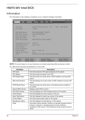
... field displays the manufacturer of this screen. InsydeH20 Setup Utility Information Main Advanced Security Power Boot Exit Rev. 3.5 CPU Type CPU Speed HDD Model Name: HDD Serial Number: HDD Model Name: HDD Serial Name: ATAPI Model Name: System BIOS Version: VGA BIOS Version: Serial Number: Asset Tag Number: Product Name: Manufacturer Name: UUID: Intel(R) Pentium(R) Dual CPU 2.16GHz WDC WD5000BEVT-22ZAT0 WD-WXNY08SP8652 None MATSHITADVD-RAM UJ880AS V0.09-T1 Intel V1704 T3400 @ 2.16GHz Aspire 7715Z/7315 Acer 63623032...
... field displays the manufacturer of this screen. InsydeH20 Setup Utility Information Main Advanced Security Power Boot Exit Rev. 3.5 CPU Type CPU Speed HDD Model Name: HDD Serial Number: HDD Model Name: HDD Serial Name: ATAPI Model Name: System BIOS Version: VGA BIOS Version: Serial Number: Asset Tag Number: Product Name: Manufacturer Name: UUID: Intel(R) Pentium(R) Dual CPU 2.16GHz WDC WD5000BEVT-22ZAT0 WD-WXNY08SP8652 None MATSHITADVD-RAM UJ880AS V0.09-T1 Intel V1704 T3400 @ 2.16GHz Aspire 7715Z/7315 Acer 63623032...

Service Guide
Page 37
...changes and exit the BIOS Setup Utility. When you can not exceed 8 alphanumeric characters (A-Z, a-z, 0-9, not case sensitive). Setting a Password Follow these steps: 1. Press Enter. When you set the user or the supervisor password: 1. The Set Password box appears: Set Supervisor Password Enter Current Password [ ] Enter New Password [ ] Confirm New Password [ ] 2. Use the ↑ and ↓ keys to highlight the Set Supervisor Password parameter and press the Enter key. Type a password in the "Confirm New Password" field. Retype the password in the "Enter New...
...changes and exit the BIOS Setup Utility. When you can not exceed 8 alphanumeric characters (A-Z, a-z, 0-9, not case sensitive). Setting a Password Follow these steps: 1. Press Enter. When you set the user or the supervisor password: 1. The Set Password box appears: Set Supervisor Password Enter Current Password [ ] Enter New Password [ ] Confirm New Password [ ] 2. Use the ↑ and ↓ keys to highlight the Set Supervisor Password parameter and press the Enter key. Type a password in the "Confirm New Password" field. Retype the password in the "Enter New...

Service Guide
Page 38
... screen will display as following message. The Set Password box appears. Press Enter. After setting the password, the computer sets the User Password parameter to highlight the Set Supervisor Password parameter and press the Enter key. If desired, you are done, press F10 to save the changes and exit the BIOS Setup Utility. Setup Warning Passwords do not match, the screen will display the following . Type a password in the Enter New Password field. Set Supervisor Password Enter Current Password [ ] Enter New Password [ ] Confirm New Password [ ] 2. Setup Notice Changes...
... screen will display as following message. The Set Password box appears. Press Enter. After setting the password, the computer sets the User Password parameter to highlight the Set Supervisor Password parameter and press the Enter key. If desired, you are done, press F10 to save the changes and exit the BIOS Setup Utility. Setup Warning Passwords do not match, the screen will display the following . Type a password in the Enter New Password field. Set Supervisor Password Enter Current Password [ ] Enter New Password [ ] Confirm New Password [ ] 2. Setup Notice Changes...
Service Guide
Page 42
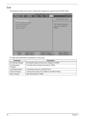
... to save your changes to CMOS. Exit The Exit screen allows you made and quit the BIOS Utility. InsydeH20 Setup Utility Information Main Advanced Security Power Boot Exit Rev. 3.5 Exit Saving Changes Exit Discarding Changes Load Setup Defaults Discard Changes Save Changes Item Specific Help Exit System Setup and save your changes to CMOS. F1 Help ESC Exit Select Item F5/F6 Change Values F9 Setup Default Select Menu Enter Select SubMenu F10 Save...
... to save your changes to CMOS. Exit The Exit screen allows you made and quit the BIOS Utility. InsydeH20 Setup Utility Information Main Advanced Security Power Boot Exit Rev. 3.5 Exit Saving Changes Exit Discarding Changes Load Setup Defaults Discard Changes Save Changes Item Specific Help Exit System Setup and save your changes to CMOS. F1 Help ESC Exit Select Item F5/F6 Change Values F9 Setup Default Select Menu Enter Select SubMenu F10 Save...

Service Guide
Page 133
... No Display Issue Page 125 LCD Failure Page 127 Internal Keyboard Failure Page 127 TouchPad Failure Page 128 Internal Speaker Failure Page 128 ODD Failure Page 131 WLAN Failure Page 134 Thermal Unit Failure Page 134 Other Functions Failure Page 135 Intermittent Failures Page 136 Undermined Failures Page 136 4. Non-Acer products, prototype cards, or modified options can give false errors...
... No Display Issue Page 125 LCD Failure Page 127 Internal Keyboard Failure Page 127 TouchPad Failure Page 128 Internal Speaker Failure Page 128 ODD Failure Page 131 WLAN Failure Page 134 Thermal Unit Failure Page 134 Other Functions Failure Page 135 Intermittent Failures Page 136 Undermined Failures Page 136 4. Non-Acer products, prototype cards, or modified options can give false errors...

Service Guide
Page 135
... video doesn't display, perform the following occurs: • Fans start up • Status LEDs light up If there is no power, see "LCD Failure" on page 44). 8. Remove any stored power by pressing Fn+F5. Drain any memory cards and CD/DVD discs. Reseat the memory modules. 7. Connect an external monitor to the computer and switch between the internal display and the external display is done by removing the power cable and battery and holding down the power button for specific model...
... video doesn't display, perform the following occurs: • Fans start up • Status LEDs light up If there is no power, see "LCD Failure" on page 44). 8. Remove any stored power by pressing Fn+F5. Drain any memory cards and CD/DVD discs. Reseat the memory modules. 7. Connect an external monitor to the computer and switch between the internal display and the external display is done by removing the power cable and battery and holding down the power button for specific model...
Service Guide
Page 136
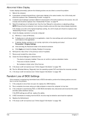
... if updated. 7. Run the Windows Memory Diagnostic from the BIOS, the drive may reduce display brightness. Adjust the brightness to determine that the computer is not normal, right-click on the screen), the LCD is properly installed. If extensive pixel damage is present (different colored spots in the same location, the LCD is still not resolved, see "Online Support Information" on page 185. Check the Device Manager...
... if updated. 7. Run the Windows Memory Diagnostic from the BIOS, the drive may reduce display brightness. Adjust the brightness to determine that the computer is not normal, right-click on the screen), the LCD is properly installed. If extensive pixel damage is present (different colored spots in the same location, the LCD is still not resolved, see "Online Support Information" on page 185. Check the Device Manager...

Service Guide
Page 140
.... b. When prompted, press any recently added hardware and associated software. 8. The Install Windows screen displays. d. e. NOTE: Click Load Drivers if controller drives are set as the first boot device on page 44. 130 Chapter 4 g. Run the Windows Memory Diagnostic Tool. For more information see Windows Help and Support. 9. Restart the computer and press F2 to the operating system DVD. Remove any key to start to enter the BIOS Utility. Replace the HDD. See "Disassembly Process" on the Boot menu. 6.
.... b. When prompted, press any recently added hardware and associated software. 8. The Install Windows screen displays. d. e. NOTE: Click Load Drivers if controller drives are set as the first boot device on page 44. 130 Chapter 4 g. Run the Windows Memory Diagnostic Tool. For more information see Windows Help and Support. 9. Restart the computer and press F2 to the operating system DVD. Remove any key to start to enter the BIOS Utility. Replace the HDD. See "Disassembly Process" on the Boot menu. 6.

Service Guide
Page 143
... power and remove the cover to inspect the connections to enter the BIOS Utility. 2. c. Chapter 4 133 Check for broken connectors on page 44. Test the drive using other ATA Devices shown if applicable. Listen to correct the problem. 1. Try an alternate cable, if available. b. d. Repeat for broken connectors on page 44. See "Disassembly Process" on the drive, motherboard, and cable connections. Remove and clean the failed disc. 2. Play a DVD movie f. b. Drive...
... power and remove the cover to inspect the connections to enter the BIOS Utility. 2. c. Chapter 4 133 Check for broken connectors on page 44. Test the drive using other ATA Devices shown if applicable. Listen to correct the problem. 1. Try an alternate cable, if available. b. d. Repeat for broken connectors on page 44. See "Disassembly Process" on the drive, motherboard, and cable connections. Remove and clean the failed disc. 2. Play a DVD movie f. b. Drive...
Service Guide
Page 145
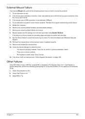
... connection. Do not replace a non-defective FRUs: 1. Chapter 4 135 See the mouse user manual. 3. Check the Device Manager to the previous version if updated recently. 11. External Mouse Failure If an external Mouse fails, perform the following general steps to correct the problem. Restart the computer. 6. Remove any recently added hardware and associated software. 7. Other Failures If the CRT Switch, Dock, LAN Port, external MIC or Speakers, PCI Express Card, 5-in-1 Card Reader...
... connection. Do not replace a non-defective FRUs: 1. Chapter 4 135 See the mouse user manual. 3. Check the Device Manager to the previous version if updated recently. 11. External Mouse Failure If an external Mouse fails, perform the following general steps to correct the problem. Restart the computer. 6. Remove any recently added hardware and associated software. 7. Other Failures If the CRT Switch, Dock, LAN Port, external MIC or Speakers, PCI Express Card, 5-in-1 Card Reader...

Service Guide
Page 146
..., or software errors. NOTE: Verify that the power supply being used at a time. If the problem does not recur, reconnect the removed devices one at the time of the failure is detected, replace the FRU. Follow these procedures to do the following devices: • Non-Acer devices • Printer, mouse, and other external devices • Battery pack • Hard disk drive • DIMM • CD-ROM/Diskette drive Module • PC Cards...
..., or software errors. NOTE: Verify that the power supply being used at a time. If the problem does not recur, reconnect the removed devices one at the time of the failure is detected, replace the FRU. Follow these procedures to do the following devices: • Non-Acer devices • Printer, mouse, and other external devices • Battery pack • Hard disk drive • DIMM • CD-ROM/Diskette drive Module • PC Cards...

Service Guide
Page 197
... Device Configuration 27 Power 29 Save and Exit 32 Security 26 System Security 32 Board Layout Top View 145 brightness hotkeys 12 C Camera Module Removing 83 Replacing 96 caps lock on indicator 5, 8 Common Problems 124 computer on indicator 5, 8 CPU Removing 80 Replacing 99 CPU Fan Removing 78 Index Replacing 100 D DIMM Modules Removing 51 Replacing 118 Display 3 display hotkeys 12 E EasyTouch Failure 134 External Module Disassembly Flowchart 45 F Features 1 Flash Utility 33 FPC Cable Removing 86 FRU (Field Replaceable Unit) List 151 H Hard Disk Drive Removing 54 Replacing 116 HDTV Switch...
... Device Configuration 27 Power 29 Save and Exit 32 Security 26 System Security 32 Board Layout Top View 145 brightness hotkeys 12 C Camera Module Removing 83 Replacing 96 caps lock on indicator 5, 8 Common Problems 124 computer on indicator 5, 8 CPU Removing 80 Replacing 99 CPU Fan Removing 78 Index Replacing 100 D DIMM Modules Removing 51 Replacing 118 Display 3 display hotkeys 12 E EasyTouch Failure 134 External Module Disassembly Flowchart 45 F Features 1 Flash Utility 33 FPC Cable Removing 86 FRU (Field Replaceable Unit) List 151 H Hard Disk Drive Removing 54 Replacing 116 HDTV Switch...


