
Aspire 5920/5920G User's Guide EN
Page 5
... product yourself, as that are covered by the operating instructions, since improper adjustment of another battery may explode if not handled properly. Warning! Do not disassemble or dispose of fire or explosion. Keep them in damage and will often require extensive work by other risks. Batteries may present a risk of them...
... product yourself, as that are covered by the operating instructions, since improper adjustment of another battery may explode if not handled properly. Warning! Do not disassemble or dispose of fire or explosion. Keep them in damage and will often require extensive work by other risks. Batteries may present a risk of them...

Aspire 5920/5920G User's Guide EN
Page 108
... AUSSETZEN PRODUCTO LÁSER DE LA CLASE I STRÅLEN. patents and other limited viewing uses only unless otherwise authorized by Macrovision. Reverse engineering or disassembly is produced with this copyright protection technology must be authorized by U.S. The CD or DVD drive's classification label (shown below) is intended for home and...
... AUSSETZEN PRODUCTO LÁSER DE LA CLASE I STRÅLEN. patents and other limited viewing uses only unless otherwise authorized by Macrovision. Reverse engineering or disassembly is produced with this copyright protection technology must be authorized by U.S. The CD or DVD drive's classification label (shown below) is intended for home and...

Aspire 5920/5920G Service Guide
Page 55
... computer, you remove the stripe cover, please be careful not to scrape the cover. During the disassembly process, group the screws with the corresponding components to avoid mismatch when putting back the components. Chapter 3 51 When you need the following tools: T Wrist ... for preventing electrostatic discharge T Small Philips screw driver T Philips screwdriver T Plastic flat head screw driver T Tweezers NOTE: The screws for maintenance and troubleshooting. Chapter 3 Machine Disassembly and Replacement This chapter contains step-by-step procedures on how to...
... computer, you remove the stripe cover, please be careful not to scrape the cover. During the disassembly process, group the screws with the corresponding components to avoid mismatch when putting back the components. Chapter 3 51 When you need the following tools: T Wrist ... for preventing electrostatic discharge T Small Philips screw driver T Philips screwdriver T Plastic flat head screw driver T Tweezers NOTE: The screws for maintenance and troubleshooting. Chapter 3 Machine Disassembly and Replacement This chapter contains step-by-step procedures on how to...

Aspire 5920/5920G Service Guide
Page 56
Turn off the power to the system and all power and signal cables from the system. 3. Remove the battery pack. 52 Chapter 3 Unplug the AC adapter and all peripherals. 2. General Information Before You Begin Before proceeding with the disassembly procedure, make sure that you do the following: 1.
Turn off the power to the system and all power and signal cables from the system. 3. Remove the battery pack. 52 Chapter 3 Unplug the AC adapter and all peripherals. 2. General Information Before You Begin Before proceeding with the disassembly procedure, make sure that you do the following: 1.
Aspire 5920/5920G Service Guide
Page 57
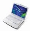
... assembly to lower case assembly on bottom side C*2 upper case assembly to remove the system board, you must first remove the keyboard, then disassemble the inside assembly frame in that need to be removed during servicing. Disassembly Procedure Flowchart The flowchart on the succeeding page gives you a graphic representation on the entire...
... assembly to lower case assembly on bottom side C*2 upper case assembly to remove the system board, you must first remove the keyboard, then disassemble the inside assembly frame in that need to be removed during servicing. Disassembly Procedure Flowchart The flowchart on the succeeding page gives you a graphic representation on the entire...
Aspire 5920/5920G Service Guide
Page 65
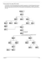
Disassembling the Lower Case Assembly Removing the Power Board 3. Disconnect the power board cable as shown. 5. Disconnect the cable from the main board. 8. Disconnect the bluetooth .... 2. Remove the power board. 6. Remove the two screws fastening the bluetooth module. 9. Carefully detach the upper case assembly from the module. Removing the Bluetooth Module 7. Disassembling the Main Unit Separate the Main Unit Into the Upper and the Lower Case Assembly 1.
Disassembling the Lower Case Assembly Removing the Power Board 3. Disconnect the power board cable as shown. 5. Disconnect the cable from the main board. 8. Disconnect the bluetooth .... 2. Remove the power board. 6. Remove the two screws fastening the bluetooth module. 9. Carefully detach the upper case assembly from the module. Removing the Bluetooth Module 7. Disassembling the Main Unit Separate the Main Unit Into the Upper and the Lower Case Assembly 1.

Aspire 5920/5920G Service Guide
Page 68
Disconnect the touchpad cables. 29. Remove the two screws fastening the touchpad board. 30. Disassembling the Upper Case Assembly Removing the Email Board 25. Turn over again and remove the DC cable and jack. Turn the lower case over the ...
Disconnect the touchpad cables. 29. Remove the two screws fastening the touchpad board. 30. Disassembling the Upper Case Assembly Removing the Email Board 25. Turn over again and remove the DC cable and jack. Turn the lower case over the ...
Aspire 5920/5920G Service Guide
Page 70
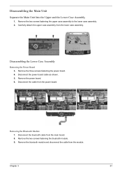
Remove the six screw rubbers as shown. 2. Detach the LCD bezel from the CCD board. 7. Disconnect the CCD cable connector from the LCD module carefully. 4. Take out the LCD from the inverter board. 6. Remove the six screws holding the LCD. 5. Disassembling the LCD Module 1. Then remove the six screws fastening the LCD bezel. 3. Detach the two inverter cable connectors from the LCD panel. 8. Remove the two screws fastening the left LCD bracket and detach it. 66 Chapter 3
Remove the six screw rubbers as shown. 2. Detach the LCD bezel from the CCD board. 7. Disconnect the CCD cable connector from the LCD module carefully. 4. Take out the LCD from the inverter board. 6. Remove the six screws holding the LCD. 5. Disassembling the LCD Module 1. Then remove the six screws fastening the LCD bezel. 3. Detach the two inverter cable connectors from the LCD panel. 8. Remove the two screws fastening the left LCD bracket and detach it. 66 Chapter 3
Aspire 5920/5920G Service Guide
Page 71
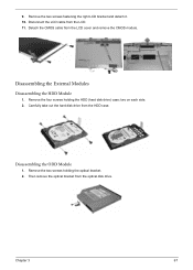
Disassembling the External Modules Disassembling the HDD Module 1. Disassembling the ODD Module 1. Then remove the optical bracket from the LCD cover and remove the CMOS module. Chapter 3 67 Detach the CMOS cable from the optical disk drive. 9. Carefully take out the hard disk drive from the LCD. 11. two on each side. 2. Remove the two screws fastening the right LCD bracket and detach it. 10. Remove the four screws holding the optical bracket. 2. Remove the two screws holding the HDD (hard disk drive) case; Disconnect the LCD cable from the HDD case.
Disassembling the External Modules Disassembling the HDD Module 1. Disassembling the ODD Module 1. Then remove the optical bracket from the LCD cover and remove the CMOS module. Chapter 3 67 Detach the CMOS cable from the optical disk drive. 9. Carefully take out the hard disk drive from the LCD. 11. two on each side. 2. Remove the two screws fastening the right LCD bracket and detach it. 10. Remove the four screws holding the optical bracket. 2. Remove the two screws holding the HDD (hard disk drive) case; Disconnect the LCD cable from the HDD case.


