Acer Aspire 5810T / 5810TG Series Service Guide
Page 7
... Specifications 1 Features 1 Aspire 5810T/5810TZ/5410T System Block Diagram 3 Aspire 5810TG System Block Diagram 4 Your Acer Notebook tour 5 Right View 8 Indicators 11 Easy-Launch Buttons 1 Touchpad basics (with two-click buttons 11 Using the Keyboard 13 Lock Keys and ...Acer GridVista (dual-display compatible 17 Hardware Specifications and Configurations 19 System Utilities 25 BIOS Setup Utility 25 Navigating the BIOS Utility 26 Information 27 Main 28 Security 30 Boot 33 Exit 34 BIOS Flash Utility 35 Remove HDD and BIOS Passwords 36 Machine Disassembly and Replacement...
... Specifications 1 Features 1 Aspire 5810T/5810TZ/5410T System Block Diagram 3 Aspire 5810TG System Block Diagram 4 Your Acer Notebook tour 5 Right View 8 Indicators 11 Easy-Launch Buttons 1 Touchpad basics (with two-click buttons 11 Using the Keyboard 13 Lock Keys and ...Acer GridVista (dual-display compatible 17 Hardware Specifications and Configurations 19 System Utilities 25 BIOS Setup Utility 25 Navigating the BIOS Utility 26 Information 27 Main 28 Security 30 Boot 33 Exit 34 BIOS Flash Utility 35 Remove HDD and BIOS Passwords 36 Machine Disassembly and Replacement...

Acer Aspire 5810T / 5810TG Series Service Guide
Page 8
...Keyboard or Auxiliary Input Device Check 78 Memory check 79 Power System Check 79 Touchpad Check 80 Power-On Self-Test (POST) Error Messages 81 Post Code Table 82 Index of Symptom-to-FRU Errors 85 Intermittent Problems 89 Undetermined Problems 90 Connector Locations 91 Top and Bottom Views 91 Aspire 5810T... Recovery by Crisis Disk 96 FRU (Field Replaceable Unit) List 99 Aspire 5810T/5810TZ/5410T Series Exploded Diagram 100 Aspire 5810TG Series Exploded Diagram 101 Model Definition and Configuration 117 Aspire 5810T/5810TZ/5410T/5810TG Series 118 Test Compatible Components...
...Keyboard or Auxiliary Input Device Check 78 Memory check 79 Power System Check 79 Touchpad Check 80 Power-On Self-Test (POST) Error Messages 81 Post Code Table 82 Index of Symptom-to-FRU Errors 85 Intermittent Problems 89 Undetermined Problems 90 Connector Locations 91 Top and Bottom Views 91 Aspire 5810T... Recovery by Crisis Disk 96 FRU (Field Replaceable Unit) List 99 Aspire 5810T/5810TZ/5410T Series Exploded Diagram 100 Aspire 5810TG Series Exploded Diagram 101 Model Definition and Configuration 117 Aspire 5810T/5810TZ/5410T/5810TG Series 118 Test Compatible Components...
Acer Aspire 5810T / 5810TG Series Service Guide
Page 86
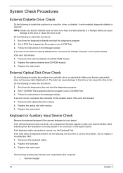
... in the message window. Do not replace a non-defective FRU: 1. Replace the external diskette drive/CD-ROM module. 3. NOTE: Make sure that the optical disk does not have more than one at a time to select the test device. 1. Replace the keyboard. 3. Replace the main board. If an error ...occurs, reconnect the connector on the system board. If the tests detect a keyboard problem, do the following to correct the problem.
... in the message window. Do not replace a non-defective FRU: 1. Replace the external diskette drive/CD-ROM module. 3. NOTE: Make sure that the optical disk does not have more than one at a time to select the test device. 1. Replace the keyboard. 3. Replace the main board. If an error ...occurs, reconnect the connector on the system board. If the tests detect a keyboard problem, do the following to correct the problem.

Acer Aspire 5810T / 5810TG Series Service Guide
Page 87
...a defect. 3. NOTE: Make sure that power is fully installed into the connector. then check that power is not correct, replace the power adapter. 2. See the following : q Replace the System board. Follow the instructions in the test items. 4. q If the problem is not correct, go to the ... check the power cord of these devices do the following figure Pin 1: +19 to main board. 2. Remove the battery pack. 2. q External keyboard If any of the power adapter for correct continuity and installation. 4. A loose connection can cause an error. Go to the next step. Memory ...
...a defect. 3. NOTE: Make sure that power is fully installed into the connector. then check that power is not correct, replace the power adapter. 2. See the following : q Replace the System board. Follow the instructions in the test items. 4. q If the problem is not correct, go to the ... check the power cord of these devices do the following figure Pin 1: +19 to main board. 2. Remove the battery pack. 2. q External keyboard If any of the power adapter for correct continuity and installation. 4. A loose connection can cause an error. Go to the next step. Memory ...


