Quick Start Guide
Page 7
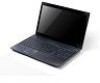
Note: Push to remove/install the card. Only one card can operate at any given time. Turns the computer on and off. The left and right buttons function like a .... Fully charged: The light shows blue when in -1 card reader Indicates the computer's battery status. 1. Indicates the computer's power status. Communication indicator Power button / indicator Keyboard Power indicator Indicates the computer's wireless connectivity device status. Accepts Secure Digital (SD), MultiMediaCard (MMC).
Note: Push to remove/install the card. Only one card can operate at any given time. Turns the computer on and off. The left and right buttons function like a .... Fully charged: The light shows blue when in -1 card reader Indicates the computer's battery status. 1. Indicates the computer's power status. Communication indicator Power button / indicator Keyboard Power indicator Indicates the computer's wireless connectivity device status. Accepts Secure Digital (SD), MultiMediaCard (MMC).
Service Guide
Page 7
...Touch Pad Basics 15 Using the Keyboard 16 Lock Keys and embedded numeric keypad 16 Windows Keys 17 Hot Keys 18 Hardware Specifications and Configurations 19 System Utilities 31 BIOS Setup Utility 31 Navigating the BIOS Utility 31 Aspire 5742/5742G/5742Z/5742ZG BIOS 32 ...Removing the Battery Pack 51 Removing the SD Dummy Card 52 Removing the ODD Module 53 Removing the Logic Lower Door 55 Removing the 3G Cover (Discrete Only 56 Removing the RTC Battery (UMA Only 57 Removing the DIMM Module 59 Removing the WLAN Module 60 Removing the HDD module Module 62 Removing the Keyboard...
...Touch Pad Basics 15 Using the Keyboard 16 Lock Keys and embedded numeric keypad 16 Windows Keys 17 Hot Keys 18 Hardware Specifications and Configurations 19 System Utilities 31 BIOS Setup Utility 31 Navigating the BIOS Utility 31 Aspire 5742/5742G/5742Z/5742ZG BIOS 32 ...Removing the Battery Pack 51 Removing the SD Dummy Card 52 Removing the ODD Module 53 Removing the Logic Lower Door 55 Removing the 3G Cover (Discrete Only 56 Removing the RTC Battery (UMA Only 57 Removing the DIMM Module 59 Removing the WLAN Module 60 Removing the HDD module Module 62 Removing the Keyboard...
Service Guide
Page 8
...LCD Module Disassembly Process 97 LCD Module Disassembly Flowchart 97 Removing the LCD Bezel 98 Removing the CCD Module 100 Removing the Inverter Module (LCD Only 101 Removing the LCD/LED Panel 104 Removing the LCD Brackets 106 Removing the LVDS Cable 107 Removing the Microphone Cable 108 Removing the Antennas 110 LCD Module Reassembly Procedure 111 Replacing... the DIMM Modules 151 Replacing the 3G Cover (Discrete Only 152 Replacing the Lower Logic Door 153 Replacing the ODD Module 154 Replacing the Keyboard 156 Replacing the SD Dummy Card 157 Replacing the Battery 158 VIII
...LCD Module Disassembly Process 97 LCD Module Disassembly Flowchart 97 Removing the LCD Bezel 98 Removing the CCD Module 100 Removing the Inverter Module (LCD Only 101 Removing the LCD/LED Panel 104 Removing the LCD Brackets 106 Removing the LVDS Cable 107 Removing the Microphone Cable 108 Removing the Antennas 110 LCD Module Reassembly Procedure 111 Replacing... the DIMM Modules 151 Replacing the 3G Cover (Discrete Only 152 Replacing the Lower Logic Door 153 Replacing the ODD Module 154 Replacing the Keyboard 156 Replacing the SD Dummy Card 157 Replacing the Battery 158 VIII
Service Guide
Page 59
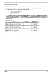
...hardware components. The disassembly process is faulty, such as the camera, antenna or LCD panel, the whole module must first remove the keyboard, then disassemble the inside assembly frame in the succeeding disassembly sections illustrate the entire disassembly sequence. Main Screw List Screw Quantity...86.R4F02.006 SCREW ASSY CPU THERMAL 4 86.R4F02.008 Chapter 3 49 Observe the order of the sequence to avoid damage to remove the mainboard, you must be disassembled outside of the LCD Module is divided into the following stages: • External module disassembly •...
...hardware components. The disassembly process is faulty, such as the camera, antenna or LCD panel, the whole module must first remove the keyboard, then disassemble the inside assembly frame in the succeeding disassembly sections illustrate the entire disassembly sequence. Main Screw List Screw Quantity...86.R4F02.006 SCREW ASSY CPU THERMAL 4 86.R4F02.008 Chapter 3 49 Observe the order of the sequence to avoid damage to remove the mainboard, you must be disassembled outside of the LCD Module is divided into the following stages: • External module disassembly •...
Service Guide
Page 60
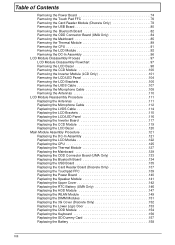
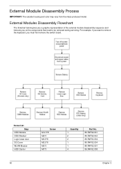
...Flowchart The flowchart below gives you a graphic representation of the external module disassembly sequence and instructs you on the components that need to remove the keyboard, you want to be removed during servicing. Screw List Step ODD Module ODD Bracket Logic lower door 3G Cover WLAN Module HDD Carrier Screw M 2.5*8 M2*3 M2.5*8... 86.R4F02.004 86.R4F02.004 86.R4F02.004 86.R4F02.001 86.R4F02.008 50 Chapter 3 For example, if you must first remove the switch board. External Module Disassembly Process IMPORTANT: The outside housing and color may vary from the mass produced model.
...Flowchart The flowchart below gives you a graphic representation of the external module disassembly sequence and instructs you on the components that need to remove the keyboard, you want to be removed during servicing. Screw List Step ODD Module ODD Bracket Logic lower door 3G Cover WLAN Module HDD Carrier Screw M 2.5*8 M2*3 M2.5*8... 86.R4F02.004 86.R4F02.004 86.R4F02.004 86.R4F02.001 86.R4F02.008 50 Chapter 3 For example, if you must first remove the switch board. External Module Disassembly Process IMPORTANT: The outside housing and color may vary from the mass produced model.

Service Guide
Page 74
Pry up the center of the keyboard and lift it up and over to remove the keyboard from the upper cover. 3. Using a flat plastic tool, release the six (6) keyboard locks to expose the keyboard FPC. 64 Chapter 3 See "Removing the Logic Lower Door" on page 55. 2. Removing the Keyboard 1.
Pry up the center of the keyboard and lift it up and over to remove the keyboard from the upper cover. 3. Using a flat plastic tool, release the six (6) keyboard locks to expose the keyboard FPC. 64 Chapter 3 See "Removing the Logic Lower Door" on page 55. 2. Removing the Keyboard 1.


