Aspire 5610 Service Guide
Page 63
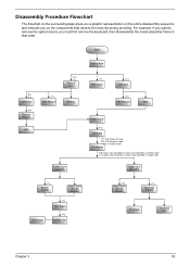
... C*2 LCD hinges to logic D*2 LCD hinges to logic C*2 on bottom side LCD Module C*8 upper case assembly to lower case assembly on bottom side C*2 upper case assembly to remove the system board, you on upper side Upper Case Assembly F*1 Modem Board Switch Board (for AS models) Lower Case F*1 Main Board F*2 Speaker Set F*2 Media Board (for AS models) F*1 Touchpad Bracket Touchpad...
... C*2 LCD hinges to logic D*2 LCD hinges to logic C*2 on bottom side LCD Module C*8 upper case assembly to lower case assembly on bottom side C*2 upper case assembly to remove the system board, you on upper side Upper Case Assembly F*1 Modem Board Switch Board (for AS models) Lower Case F*1 Main Board F*2 Speaker Set F*2 Media Board (for AS models) F*1 Touchpad Bracket Touchpad...
Aspire 5610 Service Guide
Page 70
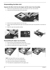
NOTE: Only Aspire 5650 series have media board. 9. Then detach the touchpad bracket from the main board. 3. Disconnect the LED board cable from the uppwer case. 60 Chapter 3 Tear off the mylar on the bottom as shown. 8. Detach the upper case assembly carefully. Remove the two screws ...fastening the media board. 7. Take out the media board cable from the upper case carefully. Remove the screws holding the touchpad bracket. 11. Remove eight screws fastening the upper case assembly and the lower case assembly on top of the touchpad bracket. 10. Detach the media board...
NOTE: Only Aspire 5650 series have media board. 9. Then detach the touchpad bracket from the main board. 3. Disconnect the LED board cable from the uppwer case. 60 Chapter 3 Tear off the mylar on the bottom as shown. 8. Detach the upper case assembly carefully. Remove the two screws ...fastening the media board. 7. Take out the media board cable from the upper case carefully. Remove the screws holding the touchpad bracket. 11. Remove eight screws fastening the upper case assembly and the lower case assembly on top of the touchpad bracket. 10. Detach the media board...

Aspire 5610 Service Guide
Page 71
Disassembling the Lower Case Assembly 1. Disconnect the modem board from the main board. 2. Detach the switch board from the main board then detach the modem board. 4. Then remove the touchpad FFC from the upper case. Detach the touchpad from the touchpad. 14. Detach the modem cable from the main board. 6. Disconnect the speaker cable from the lower case. 5. 12. Chapter 3 61 Then disconnect the microphone cable from the main baord. Disconnect the touchpad FFC. 13. Remove the screw fastening the modem board. 3.
Disassembling the Lower Case Assembly 1. Disconnect the modem board from the main board. 2. Detach the switch board from the main board then detach the modem board. 4. Then remove the touchpad FFC from the upper case. Detach the touchpad from the touchpad. 14. Detach the modem cable from the main board. 6. Disconnect the speaker cable from the lower case. 5. 12. Chapter 3 61 Then disconnect the microphone cable from the main baord. Disconnect the touchpad FFC. 13. Remove the screw fastening the modem board. 3.
Aspire 5610 Service Guide
Page 104
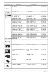
... 27.TAVV5.010 27.TAVV5.011 27.TAVV5.012 27.TAVV5.013 27.TAVV5.014 42.TAVV5.001 UPPER CASE TM W/O TV UPPER CASE TM W/O TV 60.TAVV5.001 LOWER CASE W/O CARD 1394 FIR DVI TV LOWER CASE W/O CARD 1394 FIR DVI TV 60.TAVV5.002 THERMAL DOOR THERMAL DOOR 42.TAVV5.002 MINI DOOR MINI... DOOR 42.TAVV5.003 T/P BRACKET W/MYLAR T/P BRACKET W/MYLAR 33.TAVV5.001 94 Chapter 6 CATEGORY PARTNAME RJ-11 CABLE DESCRIPTION RJ-11 CABLE Acer PN 50.TAVV5.002 BLUETOOTH...
... 27.TAVV5.010 27.TAVV5.011 27.TAVV5.012 27.TAVV5.013 27.TAVV5.014 42.TAVV5.001 UPPER CASE TM W/O TV UPPER CASE TM W/O TV 60.TAVV5.001 LOWER CASE W/O CARD 1394 FIR DVI TV LOWER CASE W/O CARD 1394 FIR DVI TV 60.TAVV5.002 THERMAL DOOR THERMAL DOOR 42.TAVV5.002 MINI DOOR MINI... DOOR 42.TAVV5.003 T/P BRACKET W/MYLAR T/P BRACKET W/MYLAR 33.TAVV5.001 94 Chapter 6 CATEGORY PARTNAME RJ-11 CABLE DESCRIPTION RJ-11 CABLE Acer PN 50.TAVV5.002 BLUETOOTH...


