Aspire 5534 Service Guide
Page 7
... Remove HDD/BIOS Password Utilities 37 Removing BIOS Passwords 38 Miscellaneous Utilities 39 Machine Disassembly and Replacement 43 Disassembly Requirements 43 Related Information 43 43 General Information 44 Pre-disassembly Instructions 44 Disassembly Process 44 External Module Disassembly Process 45 External Modules Disassembly Flowchart 45 Removing the Battery Pack 46 Removing the Hard Disk Drive Module...
... Remove HDD/BIOS Password Utilities 37 Removing BIOS Passwords 38 Miscellaneous Utilities 39 Machine Disassembly and Replacement 43 Disassembly Requirements 43 Related Information 43 43 General Information 44 Pre-disassembly Instructions 44 Disassembly Process 44 External Module Disassembly Process 45 External Modules Disassembly Flowchart 45 Removing the Battery Pack 46 Removing the Hard Disk Drive Module...
Aspire 5534 Service Guide
Page 8
... the Mainboard 81 Removing the LCD Module 84 Removing the Fan 86 Removing the Thermal Module 88 Removing the CPU 89 LCD Module Disassembly Process 90 LCD Module Disassembly Flowchart 90 Removing the LCD Bezel 91 Removing the Camera Board 94 Removing the LCD Panel 95 Removing the FPC Cable 96 Removing...
... the Mainboard 81 Removing the LCD Module 84 Removing the Fan 86 Removing the Thermal Module 88 Removing the CPU 89 LCD Module Disassembly Process 90 LCD Module Disassembly Flowchart 90 Removing the LCD Bezel 91 Removing the Camera Board 94 Removing the LCD Panel 95 Removing the FPC Cable 96 Removing...

Aspire 5534 Service Guide
Page 53
...Replacement This chapter contains step-by-step procedures on how to avoid mismatch when putting back the components. Disassembly Requirements To disassemble the computer, you need the following tools: q Wrist grounding strap and conductive mat for preventing electrostatic ...q Plastic flat screwdriver q Plastic tweezers NOTE: The screws for maintenance and troubleshooting. During the disassembly process, group the screws with the corresponding components to disassemble the notebook computer for the different components vary in size. During the removal and replacement of components...
...Replacement This chapter contains step-by-step procedures on how to avoid mismatch when putting back the components. Disassembly Requirements To disassemble the computer, you need the following tools: q Wrist grounding strap and conductive mat for preventing electrostatic ...q Plastic flat screwdriver q Plastic tweezers NOTE: The screws for maintenance and troubleshooting. During the disassembly process, group the screws with the corresponding components to disassemble the notebook computer for the different components vary in size. During the removal and replacement of components...
Aspire 5534 Service Guide
Page 54
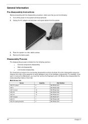
...86.PEA02.001 86.PEA02.009 86.PEA02.004 44 Chapter 3 Place the system on a flat, stable surface. 4. Disassembly Process The disassembly process is divided into the following : 1. Remove the battery pack. Observe the order of the sequence to avoid damage ...the system. 3. General Information Pre-disassembly Instructions Before proceeding with the disassembly procedure, make sure that you must first remove the Keyboard, and LCD Module then disassemble the inside assembly frame in the succeeding disassembly sections illustrate the entire disassembly sequence. Unplug the AC adapter and...
...86.PEA02.001 86.PEA02.009 86.PEA02.004 44 Chapter 3 Place the system on a flat, stable surface. 4. Disassembly Process The disassembly process is divided into the following : 1. Remove the battery pack. Observe the order of the sequence to avoid damage ...the system. 3. General Information Pre-disassembly Instructions Before proceeding with the disassembly procedure, make sure that you must first remove the Keyboard, and LCD Module then disassemble the inside assembly frame in the succeeding disassembly sections illustrate the entire disassembly sequence. Unplug the AC adapter and...

Aspire 5534 Service Guide
Page 55
... may not represent the final product color or configuration. External Modules Disassembly Flowchart Turn off system and peripherals power Disconnect power and signal cables from system Remove Battery Remove Dummy Card Remove Lower Covers Remove DIMMs Remove ...
... may not represent the final product color or configuration. External Modules Disassembly Flowchart Turn off system and peripherals power Disconnect power and signal cables from system Remove Battery Remove Dummy Card Remove Lower Covers Remove DIMMs Remove ...
Aspire 5534 Service Guide
Page 68
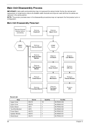
Main Unit Disassembly Flowchart Remove External Modules before proceeding Remove Keyboard Remove Upper Cover Upper Cover Remove Function Board Lower Cover Remove Right Speaker Module Remove Left Speaker ... Chapter 3 During the removal and replacement of components, ensure all available cable channels and clips are used and that the cables are replaced in the disassembly procedures may not represent the actual model. NOTE: The product previews seen in the same position. Main Unit...
Main Unit Disassembly Flowchart Remove External Modules before proceeding Remove Keyboard Remove Upper Cover Upper Cover Remove Function Board Lower Cover Remove Right Speaker Module Remove Left Speaker ... Chapter 3 During the removal and replacement of components, ensure all available cable channels and clips are used and that the cables are replaced in the disassembly procedures may not represent the actual model. NOTE: The product previews seen in the same position. Main Unit...

Aspire 5534 Service Guide
Page 72
Step Upper Cover Size M2.5*8 Quantity 18 Screw Type 3. Removing the Upper Cover 1. Disconnect the Speaker Cable as shown. 62 Chapter 3 Remove all external modules. Remove the screws securing the Upper Cover to the Lower Cover. See "External Modules Disassembly Flowchart" on page 45. 2. Turn the computer over and disconnect the following cables from the Mainboard: a.
Step Upper Cover Size M2.5*8 Quantity 18 Screw Type 3. Removing the Upper Cover 1. Disconnect the Speaker Cable as shown. 62 Chapter 3 Remove all external modules. Remove the screws securing the Upper Cover to the Lower Cover. See "External Modules Disassembly Flowchart" on page 45. 2. Turn the computer over and disconnect the following cables from the Mainboard: a.
Aspire 5534 Service Guide
Page 100
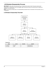
... and clips are used and that the cables are replaced in the disassembly procedures may not represent the actual model. LCD Module Disassembly Process IMPORTANT: Cable paths and positioning may not represent the final product color or configuration. LCD Module Disassembly Flowchart Remove LCD Panel from Main Unit before proceeding Remove LCD Bezel...
... and clips are used and that the cables are replaced in the disassembly procedures may not represent the actual model. LCD Module Disassembly Process IMPORTANT: Cable paths and positioning may not represent the final product color or configuration. LCD Module Disassembly Flowchart Remove LCD Panel from Main Unit before proceeding Remove LCD Bezel...
Aspire 5534 Service Guide
Page 160
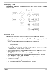
... power button for specific model procedures. 2. Drain any memory cards and CD/DVD discs. If the POST or video appears on the external display, see "Disassembly Process" on page 191. Make sure the computer has power by pressing Fn+F5 (on page 149. 3. If the Issue is no power, see "Power...
... power button for specific model procedures. 2. Drain any memory cards and CD/DVD discs. If the POST or video appears on the external display, see "Disassembly Process" on page 191. Make sure the computer has power by pressing Fn+F5 (on page 149. 3. If the Issue is no power, see "Power...
Aspire 5534 Service Guide
Page 161
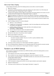
See "Disassembly Process" on page 52. 3. NOTE: Ensure that : • The device is properly installed. Check the display resolution is experiencing HDD or ODD BIOS information loss, ... the display. If the computer is correctly configured: a. If the Issue is still not resolved, see "Online Support Information" on page 191. See "Disassembly Process" on page 52. 4. See "Disassembly Process" on adjusting settings. e. If the Issue is still not resolved, see "Online Support Information" on page 191. 10. If the Issue...
See "Disassembly Process" on page 52. 3. NOTE: Ensure that : • The device is properly installed. Check the display resolution is experiencing HDD or ODD BIOS information loss, ... the display. If the computer is correctly configured: a. If the Issue is still not resolved, see "Online Support Information" on page 191. See "Disassembly Process" on page 52. 4. See "Disassembly Process" on adjusting settings. e. If the Issue is still not resolved, see "Online Support Information" on page 191. 10. If the Issue...
Aspire 5534 Service Guide
Page 166
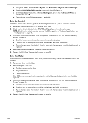
... Help and Support. 9. Run Windows Check Disk by entering chkdsk /r from a known good date using up-to-date software to enter the BIOS Utility. See "Disassembly Process" on the Boot menu. 6. b. Select the appropriate operating system, and click Next. Check the BIOS settings are correct and that CD/DVD drive is...
... Help and Support. 9. Run Windows Check Disk by entering chkdsk /r from a known good date using up-to-date software to enter the BIOS Utility. See "Disassembly Process" on the Boot menu. 6. b. Select the appropriate operating system, and click Next. Check the BIOS settings are correct and that CD/DVD drive is...
Aspire 5534 Service Guide
Page 169
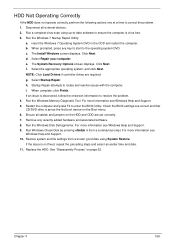
... to correct the problem. 1. b. Navigate to the ODD. Double-click IDE ATA/ATAPI controllers, then right-click ATA Device 0. See "Disassembly Process" on the drive, motherboard, and cables. Play a DVD movie f. Drive Not Detected If Windows cannot detect the drive, perform the...180; Device Manager. Check for broken connectors on page 52. 159 Chapter 4 c. d. a. Check for broken connectors on page 52. See "Disassembly Process" on the drive, motherboard, and cables. b. Ensure that the entry is detected in the drive, perform the following actions one of ...
... to correct the problem. 1. b. Navigate to the ODD. Double-click IDE ATA/ATAPI controllers, then right-click ATA Device 0. See "Disassembly Process" on the drive, motherboard, and cables. Play a DVD movie f. Drive Not Detected If Windows cannot detect the drive, perform the...180; Device Manager. Check for broken connectors on page 52. 159 Chapter 4 c. d. a. Check for broken connectors on page 52. See "Disassembly Process" on the drive, motherboard, and cables. b. Ensure that the entry is detected in the drive, perform the following actions one of ...
Aspire 5534 Service Guide
Page 221
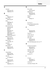
... CPU Fan Replacing 116 Index D DC-In Cable Removing 80 DIMM Module Removing 53 Replacing 139 Display 3 display hotkeys 12 E Euro Key 13 External Module Disassembly Flowchart 45 F Fan Removing 86 Replacing 116 Features 1 FLASH Utility 34 Flash Utility 34 FPC Cable Removing 96 Replacing 107 FRU (Field Replaceable Unit) List...
... CPU Fan Replacing 116 Index D DC-In Cable Removing 80 DIMM Module Removing 53 Replacing 139 Display 3 display hotkeys 12 E Euro Key 13 External Module Disassembly Flowchart 45 F Fan Removing 86 Replacing 116 Features 1 FLASH Utility 34 Flash Utility 34 FPC Cable Removing 96 Replacing 107 FRU (Field Replaceable Unit) List...
Aspire 5534 Service Guide
Page 222
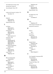
... Removing 98 Replacing 105 LCD Cable Removing 96, 107 LCD Failure 152 LCD Module Disassembly 90 Reassembly 103 Removing 84 Replacing 112 LCD Module Disassembly Flowchart 90 LCD Panel Removing 95 Replacing 108 Lower Covers Replacing 145 M Main Unit Disassembly Flowchart 58 Mainboard Removing 81 Replacing 118 media access on indicator 8 Media Board...
... Removing 98 Replacing 105 LCD Cable Removing 96, 107 LCD Failure 152 LCD Module Disassembly 90 Reassembly 103 Removing 84 Replacing 112 LCD Module Disassembly Flowchart 90 LCD Panel Removing 95 Replacing 108 Lower Covers Replacing 145 M Main Unit Disassembly Flowchart 58 Mainboard Removing 81 Replacing 118 media access on indicator 8 Media Board...


