Acer Aspire 5534 Notebook Series Start Guide
Page 3
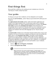
... mobile computing needs. This guide contains detailed information on the screen to access it contains warranty information and the general regulations and safety notices for your Acer notebook, we have designed a set of your notebook. For instructions on your new computer. It covers basic topics such as system utilities, data recovery, expansion options and troubleshooting. Note: Viewing the file requires Adobe Reader. It is not installed on...
... mobile computing needs. This guide contains detailed information on the screen to access it contains warranty information and the general regulations and safety notices for your Acer notebook, we have designed a set of your notebook. For instructions on your new computer. It covers basic topics such as system utilities, data recovery, expansion options and troubleshooting. Note: Viewing the file requires Adobe Reader. It is not installed on...
Acer Aspire 5534 Notebook Series Start Guide
Page 6
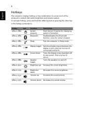
...'s controls like screen brightness and volume output. Increases the sound volume. + < > Volume down Volume up Increases the screen brightness. + < > + < > Brightness down Decreases the sound volume. 6 English Hotkeys The computer employs hotkeys or key combinations to save power. Hotkey Icon + + + Function System property Bluetooth Sleep Description Starts System Property for certain models) Puts the computer in the hotkey combination. Enables/disables the Bluetooth function. (only for displaying system information. Brightness up Decreases the screen brightness...
...'s controls like screen brightness and volume output. Increases the sound volume. + < > Volume down Volume up Increases the screen brightness. + < > + < > Brightness down Decreases the sound volume. 6 English Hotkeys The computer employs hotkeys or key combinations to save power. Hotkey Icon + + + Function System property Bluetooth Sleep Description Starts System Property for certain models) Puts the computer in the hotkey combination. Enables/disables the Bluetooth function. (only for displaying system information. Brightness up Decreases the screen brightness...
Acer Aspire 5534 Notebook Series Start Guide
Page 8
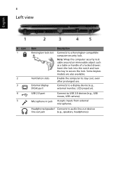
... the key to USB 2.0 devices (e.g., USB mouse, USB camera). USB 2.0 port Microphone-in jack Connect to secure the lock. Headphones/speaker/ Connects to a Kensington-compatible computer security lock. 8 Left view English # Icon 1 2 3 4 5 Item Kensington lock slot Ventilation slots External display (VGA) port Description Connects to audio line-out devices line-out jack (e.g., speakers, headphones). Enable the computer to a display device (e.g., external monitor, LCD projector). Accepts inputs from external microphones. Connects to stay cool, even after prolonged use.
... the key to USB 2.0 devices (e.g., USB mouse, USB camera). USB 2.0 port Microphone-in jack Connect to secure the lock. Headphones/speaker/ Connects to a Kensington-compatible computer security lock. 8 Left view English # Icon 1 2 3 4 5 Item Kensington lock slot Ventilation slots External display (VGA) port Description Connects to audio line-out devices line-out jack (e.g., speakers, headphones). Enable the computer to a display device (e.g., external monitor, LCD projector). Accepts inputs from external microphones. Connects to stay cool, even after prolonged use.
Acer Aspire 5534 Notebook Series Start Guide
Page 11
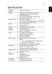
... BIOS user, supervisor, HDD passwords Kensington lock slot ACPI 3.0 48.8 W 4400 mAh 3-pin 65 W AC adapter ENERGY STAR®* 99-/100-/103-key keyboard Touchpad pointing device 11 English Specifications Operating • system Platform • • • • • System memory • • Display • • Graphics • Storage • subsystem • • Audio • • • • Communication • • • Dimensions • • Privacy control...
... BIOS user, supervisor, HDD passwords Kensington lock slot ACPI 3.0 48.8 W 4400 mAh 3-pin 65 W AC adapter ENERGY STAR®* 99-/100-/103-key keyboard Touchpad pointing device 11 English Specifications Operating • system Platform • • • • • System memory • • Display • • Graphics • Storage • subsystem • • Audio • • • • Communication • • • Dimensions • • Privacy control...
Aspire 5534 Service Guide
Page 7
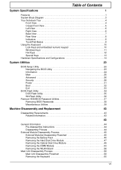
... 7 Rear View 8 Indicators 8 TouchPad Basics 9 Using the Keyboard 10 Lock Keys and embedded numeric keypad 10 Windows Keys 11 Hot Keys 12 Special Keys 13 Hardware Specifications and Configurations 14 System Utilities 23 BIOS Setup Utility 23 Navigating the BIOS Utility 23 Information 24 Main 25 Advanced 26 Security 28 Power 31 Boot 32 Exit 33 BIOS Flash Utility 34 DOS Flash Utility 35 WinFlash Utility 36 Remove HDD/BIOS Password Utilities 37 Removing BIOS Passwords 38 Miscellaneous Utilities 39 Machine Disassembly and Replacement 43 Disassembly Requirements 43...
... 7 Rear View 8 Indicators 8 TouchPad Basics 9 Using the Keyboard 10 Lock Keys and embedded numeric keypad 10 Windows Keys 11 Hot Keys 12 Special Keys 13 Hardware Specifications and Configurations 14 System Utilities 23 BIOS Setup Utility 23 Navigating the BIOS Utility 23 Information 24 Main 25 Advanced 26 Security 28 Power 31 Boot 32 Exit 33 BIOS Flash Utility 34 DOS Flash Utility 35 WinFlash Utility 36 Remove HDD/BIOS Password Utilities 37 Removing BIOS Passwords 38 Miscellaneous Utilities 39 Machine Disassembly and Replacement 43 Disassembly Requirements 43...
Aspire 5534 Service Guide
Page 8
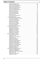
... Upper Cover 62 Removing the Button Board 66 Removing the Touchpad Bracket 68 Removing the Power Board 70 Removing the Speaker Modules 72 Removing the Media Board 74 Removing the Bluetooth Module 76 Removing the I/O Board 77 Removing the DC-In Cable 80 Removing the Mainboard 81 Removing the LCD Module 84 Removing the Fan 86 Removing the Thermal Module 88 Removing the CPU 89 LCD Module Disassembly Process 90 LCD Module Disassembly Flowchart 90 Removing the LCD Bezel 91 Removing the Camera Board 94 Removing the LCD Panel 95 Removing the FPC Cable 96 Removing the LCD Brackets...
... Upper Cover 62 Removing the Button Board 66 Removing the Touchpad Bracket 68 Removing the Power Board 70 Removing the Speaker Modules 72 Removing the Media Board 74 Removing the Bluetooth Module 76 Removing the I/O Board 77 Removing the DC-In Cable 80 Removing the Mainboard 81 Removing the LCD Module 84 Removing the Fan 86 Removing the Thermal Module 88 Removing the CPU 89 LCD Module Disassembly Process 90 LCD Module Disassembly Flowchart 90 Removing the LCD Bezel 91 Removing the Camera Board 94 Removing the LCD Panel 95 Removing the FPC Cable 96 Removing the LCD Brackets...
Aspire 5534 Service Guide
Page 9
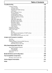
... 164 Intermittent Problems 164 Undetermined Problems 165 POST Code Tables 166 Sec 166 Memory 166 DLL Timing Control Registers, RCOMP settings 167 BDS & Specific action 168 Each PEIM entry point used in 80_PORT 168 Jumper and Connector Locations 173 Top View 173 Bottom View 174 Clearing Password Check and BIOS Recovery 175 Clearing Password Check 175 BIOS Recovery by Crisis Disk 176 FRU (Field Replaceable Unit) List 177 Aspire 5534 Exploded Diagrams 178...
... 164 Intermittent Problems 164 Undetermined Problems 165 POST Code Tables 166 Sec 166 Memory 166 DLL Timing Control Registers, RCOMP settings 167 BDS & Specific action 168 Each PEIM entry point used in 80_PORT 168 Jumper and Connector Locations 173 Top View 173 Bottom View 174 Clearing Password Check and BIOS Recovery 175 Clearing Password Check 175 BIOS Recovery by Crisis Disk 176 FRU (Field Replaceable Unit) List 177 Aspire 5534 Exploded Diagrams 178...
Aspire 5534 Service Guide
Page 16
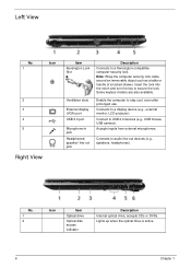
... 2.0 port Microphone-in jack Headphones/ speaker/ line-out jack Description Connects to secure the lock. Insert the lock into the notch and turn the key to a Kensington-compatible computer security lock. Connect to audio line-out devices (e.g., speakers, headphones). No. 1 2 Icon Item Optical drive Optical disk access indicator Description Internal optical drive; Connects to USB 2.0 devices (e.g., USB mouse, USB camera). Connects to stay cool, even after prolonged use. Some keyless models are also available. Enable the computer to a display device (e.g., external monitor, LCD...
... 2.0 port Microphone-in jack Headphones/ speaker/ line-out jack Description Connects to secure the lock. Insert the lock into the notch and turn the key to a Kensington-compatible computer security lock. Connect to audio line-out devices (e.g., speakers, headphones). No. 1 2 Icon Item Optical drive Optical disk access indicator Description Internal optical drive; Connects to USB 2.0 devices (e.g., USB mouse, USB camera). Connects to stay cool, even after prolonged use. Some keyless models are also available. Enable the computer to a display device (e.g., external monitor, LCD...
Aspire 5534 Service Guide
Page 39
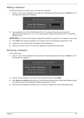
.... 5. Removing a Password Follow these steps as you are done, press F10 to save the changes and exit the BIOS Setup Utility. The Set Supervisor Password box appears: Set Supervisor Password Enter New Password [ ] Confirm New Password [ ] 2. Use the ↑ and ↓ keys to "Clear". 4. Type the current password in the Enter New Password and Confirm New Password fields. After setting the password, the computer sets the User Password parameter to highlight the Set Supervisor Password parameter and press the Enter key. Press Enter twice without typing...
.... 5. Removing a Password Follow these steps as you are done, press F10 to save the changes and exit the BIOS Setup Utility. The Set Supervisor Password box appears: Set Supervisor Password Enter New Password [ ] Confirm New Password [ ] 2. Use the ↑ and ↓ keys to "Clear". 4. Type the current password in the Enter New Password and Confirm New Password fields. After setting the password, the computer sets the User Password parameter to highlight the Set Supervisor Password parameter and press the Enter key. Press Enter twice without typing...
Aspire 5534 Service Guide
Page 40
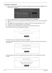
... Enter. 3. If the current password entered does not match the actual current password, the screen will display as following message. Type a password in the Enter New Password field. After setting the password, the computer sets the User Password parameter to highlight the Set Supervisor Password parameter and press the Enter key. If desired, you are done, press F10 to save the changes and exit the BIOS Setup Utility. Setup Notice Changes have been saved. [Continue] The password setting...
... Enter. 3. If the current password entered does not match the actual current password, the screen will display as following message. Type a password in the Enter New Password field. After setting the password, the computer sets the User Password parameter to highlight the Set Supervisor Password parameter and press the Enter key. If desired, you are done, press F10 to save the changes and exit the BIOS Setup Utility. Setup Notice Changes have been saved. [Continue] The password setting...
Aspire 5534 Service Guide
Page 43
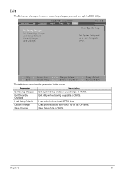
... Change Values F9 Setup Default Select Menu Enter Select SubMenu F10 Save and Exit The table below describes the parameters in this screen. Load previous values from CMOS for all SETUP items. Save Setup Data to CMOS. Exit utility without saving setup data to CMOS. InsydeH20 Setup Utility Information Main Advanced Security Power Boot Exit Rev. 3.5 Exit Saving Changes Exit Discarding Changes Load Setup Defaults Discard Changes Save Changes Item Specific Help Exit System Setup...
... Change Values F9 Setup Default Select Menu Enter Select SubMenu F10 Save and Exit The table below describes the parameters in this screen. Load previous values from CMOS for all SETUP items. Save Setup Data to CMOS. Exit utility without saving setup data to CMOS. InsydeH20 Setup Utility Information Main Advanced Security Power Boot Exit Rev. 3.5 Exit Saving Changes Exit Discarding Changes Load Setup Defaults Discard Changes Save Changes Item Specific Help Exit System Setup...
Aspire 5534 Service Guide
Page 68
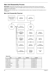
... used and that the cables are replaced in the disassembly procedures may not represent the actual model. Main Unit Disassembly Flowchart Remove External Modules before proceeding Remove Keyboard Remove Upper Cover Upper Cover Remove Function Board Lower Cover Remove Right Speaker Module Remove Left Speaker Module Remove I/O Board Remove Power Socket Remove LCD Module Remove CPU Fan Remove Power Board Remove Mainboard Remove Thermal Module Screw List Step Upper Cover Upper Cover Button Board TouchPad Bracket Power Board Speaker Module Media Board 58 Remove Touchpad Board Remove...
... used and that the cables are replaced in the disassembly procedures may not represent the actual model. Main Unit Disassembly Flowchart Remove External Modules before proceeding Remove Keyboard Remove Upper Cover Upper Cover Remove Function Board Lower Cover Remove Right Speaker Module Remove Left Speaker Module Remove I/O Board Remove Power Socket Remove LCD Module Remove CPU Fan Remove Power Board Remove Mainboard Remove Thermal Module Screw List Step Upper Cover Upper Cover Button Board TouchPad Bracket Power Board Speaker Module Media Board 58 Remove Touchpad Board Remove...
Aspire 5534 Service Guide
Page 158
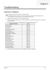
... (Verified) Go To Power On Issue Page 149 No Display Issue Page 150 LCD Failure Page 152 Internal Keyboard Failure Page 152 Touchpad Failure Page 153 Internal Speaker Failure Page 153 Internal Microphone Failure Page 155 ODD Failure Page 157 Rightside USB Failure Page 160 Modem Failure Page 161 WLAN/WiMAX Failure Page 161 Bluetooth Failure Page 162 Function Button Failure Page 162...
... (Verified) Go To Power On Issue Page 149 No Display Issue Page 150 LCD Failure Page 152 Internal Keyboard Failure Page 152 Touchpad Failure Page 153 Internal Speaker Failure Page 153 Internal Microphone Failure Page 155 ODD Failure Page 157 Rightside USB Failure Page 160 Modem Failure Page 161 WLAN/WiMAX Failure Page 161 Bluetooth Failure Page 162 Function Button Failure Page 162...
Aspire 5534 Service Guide
Page 160
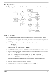
.... Make sure the computer has power by removing the power cable and battery and holding down the power button for specific model procedures. 2. Chapter 4 150 Drain any memory cards and CD/DVD discs. If the computer boots correctly, add the devices one by pressing Fn+F5 (on this notebook model, switching between the internal display and the external display is by one until the failure point is selected. Reseat the memory modules. 7. Remove any stored power by...
.... Make sure the computer has power by removing the power cable and battery and holding down the power button for specific model procedures. 2. Chapter 4 150 Drain any memory cards and CD/DVD discs. If the computer boots correctly, add the devices one by pressing Fn+F5 (on this notebook model, switching between the internal display and the external display is by one until the failure point is selected. Reseat the memory modules. 7. Remove any stored power by...
Aspire 5534 Service Guide
Page 161
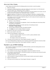
... reconnect the power and data cables between devices. If HDD information is not running on page 191. 10. See "Disassembly Process" on adjusting settings. See the User Manual for instructions on page 52. 3. NOTE: Ensure that : • The device is experiencing intermittent loss of BIOS information, perform the following actions one year old, replace the CMOS battery. 2. Minimize or close all Windows. Roll back the video driver to...
... reconnect the power and data cables between devices. If HDD information is not running on page 191. 10. See "Disassembly Process" on adjusting settings. See the User Manual for instructions on page 52. 3. NOTE: Ensure that : • The device is experiencing intermittent loss of BIOS information, perform the following actions one year old, replace the CMOS battery. 2. Minimize or close all Windows. Roll back the video driver to...
Aspire 5534 Service Guide
Page 166
... Windows Memory Diagnostic Tool. The Install Windows screen displays. Select the appropriate operating system, and click Next. Ensure all external devices. 2. Remove any key to start to enter the BIOS Utility. If the issue is set correctly. 7. i. For more information see Windows Help and Support. 9. Run Windows Check Disk by entering chkdsk /r from a known good date using up-to-date software to locate and resolve issues with the computer. f. NOTE: Click Load Drivers if controller drives are set...
... Windows Memory Diagnostic Tool. The Install Windows screen displays. Select the appropriate operating system, and click Next. Ensure all external devices. 2. Remove any key to start to enter the BIOS Utility. If the issue is set correctly. 7. i. For more information see Windows Help and Support. 9. Run Windows Check Disk by entering chkdsk /r from a known good date using up-to-date software to locate and resolve issues with the computer. f. NOTE: Click Load Drivers if controller drives are set...
Aspire 5534 Service Guide
Page 169
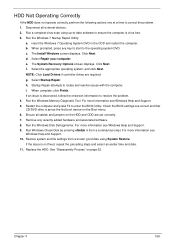
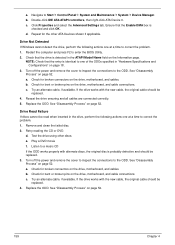
... Start´ Control Panel´ System and Maintenance´ System´ Device Manager. a. Test the drive using other ATA Devices shown if applicable. Navigate to enter the BIOS Utility. 2. Check for bent or broken pins on the drive, motherboard, and cables. c. Replace the ODD. Retry reading the CD or DVD. e. Listen to correct the problem. 1. If the drive works with the new cable, the original cable should be read when inserted in "Hardware Specifications and Configurations...
... Start´ Control Panel´ System and Maintenance´ System´ Device Manager. a. Test the drive using other ATA Devices shown if applicable. Navigate to enter the BIOS Utility. 2. Check for bent or broken pins on the drive, motherboard, and cables. c. Replace the ODD. Retry reading the CD or DVD. e. Listen to correct the problem. 1. If the drive works with the new cable, the original cable should be read when inserted in "Hardware Specifications and Configurations...
Aspire 5534 Service Guide
Page 174
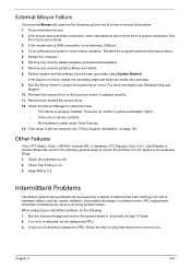
... CRT Switch, Dock, LAN Port, external MIC or Speakers, PCI Express Card, 5-in loop mode at a time to correct the problem. 1. Run the advanced diagnostic test for errors. Remove any recently added software and reboot. 8. FRU replacement should be caused by a variety of reasons that have nothing to do the following: 1. Chapter 4 164 If the mouse uses a USB connection, try an alternate USB port. 4. Restore system and file settings from...
... CRT Switch, Dock, LAN Port, external MIC or Speakers, PCI Express Card, 5-in loop mode at a time to correct the problem. 1. Run the advanced diagnostic test for errors. Remove any recently added software and reboot. 8. FRU replacement should be caused by a variety of reasons that have nothing to do the following: 1. Chapter 4 164 If the mouse uses a USB connection, try an alternate USB port. 4. Restore system and file settings from...
Aspire 5534 Service Guide
Page 185
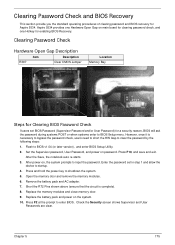
... main board for clearing password check, and one Hotkey for enabling BIOS Recovery. Open the memory door and remove the memory modules. 6. Chapter 5 175 Check the Security screen shows Supervisor and User Passwords are clear. Clearing Password Check Hardware Open Gap Description Item Description R397 Clear CMOS Jumper Location Memory Bay Steps for Clearing BIOS Password Check If users set in step 1 and allow the device to startup. 4. Press and hold the power key to BIOS v1.04 (or later version), and enter BIOS Setup Utility. 2. Clearing Password Check and BIOS Recovery...
... main board for clearing password check, and one Hotkey for enabling BIOS Recovery. Open the memory door and remove the memory modules. 6. Chapter 5 175 Check the Security screen shows Supervisor and User Passwords are clear. Clearing Password Check Hardware Open Gap Description Item Description R397 Clear CMOS Jumper Location Memory Bay Steps for Clearing BIOS Password Check If users set in step 1 and allow the device to startup. 4. Press and hold the power key to BIOS v1.04 (or later version), and enter BIOS Setup Utility. 2. Clearing Password Check and BIOS Recovery...
Aspire 5534 Service Guide
Page 222
... 136 Keyboard Failure 152 L LCD Bezel Removing 91 Replacing 109 LCD Brackets Removing 98 Replacing 105 LCD Cable Removing 96, 107 LCD Failure 152 LCD Module Disassembly 90 Reassembly 103 Removing 84 Replacing 112 LCD Module Disassembly Flowchart 90 LCD Panel Removing 95 Replacing 108 Lower Covers Replacing 145 M Main Unit Disassembly Flowchart 58 Mainboard Removing 81 Replacing 118 media access on indicator 8 Media Board Removing 74 212 Replacing 124 Microphone Removing 99 Replacing 104 Model Definition 188 N No Display Issue 150 num lock on indicator 8 O ODD Replacing 143 Online Support...
... 136 Keyboard Failure 152 L LCD Bezel Removing 91 Replacing 109 LCD Brackets Removing 98 Replacing 105 LCD Cable Removing 96, 107 LCD Failure 152 LCD Module Disassembly 90 Reassembly 103 Removing 84 Replacing 112 LCD Module Disassembly Flowchart 90 LCD Panel Removing 95 Replacing 108 Lower Covers Replacing 145 M Main Unit Disassembly Flowchart 58 Mainboard Removing 81 Replacing 118 media access on indicator 8 Media Board Removing 74 212 Replacing 124 Microphone Removing 99 Replacing 104 Model Definition 188 N No Display Issue 150 num lock on indicator 8 O ODD Replacing 143 Online Support...


