Aspire 5510 Service Guide
Page 6
... 29 BIOS Setup Utility 29 Information 30 Main 32 Advanced 34 Security 35 Boot 38 Exit 39 Chapter 3 Machine Disassembly and Replacement 40 General Information 41 Disassembly Procedure Flowchart 42 Removing the Battery Pack 44 Removing the HDD Module/the Memory and the Wireless LAN Card/the ...Thermal Module and the CPU/ODD Module and LCD Module 45 Disassembling the Main Unit 49 Disassembling the LCD Module 53 Disassembling the External Modules 55 Chapter 4 Troubleshooting 56 System Check Procedures 57 Power-On Self-Test (POST) Error ...
... 29 BIOS Setup Utility 29 Information 30 Main 32 Advanced 34 Security 35 Boot 38 Exit 39 Chapter 3 Machine Disassembly and Replacement 40 General Information 41 Disassembly Procedure Flowchart 42 Removing the Battery Pack 44 Removing the HDD Module/the Memory and the Wireless LAN Card/the ...Thermal Module and the CPU/ODD Module and LCD Module 45 Disassembling the Main Unit 49 Disassembling the LCD Module 53 Disassembling the External Modules 55 Chapter 4 Troubleshooting 56 System Check Procedures 57 Power-On Self-Test (POST) Error ...
Aspire 5510 Service Guide
Page 46
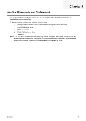
...screw driver T Tweezers NOTE: The screws for maintenance and troubleshooting. Machine Disassembly and Replacement Chapter 3 This chapter contains step-by-step procedures on how to scrape the cover. During the disassembly process, group the screws with the corresponding components to avoid mismatch when ...putting back the components. To disassemble the computer, you remove the stripe cover, please be careful not to disassemble the notebook computer for the different...
...screw driver T Tweezers NOTE: The screws for maintenance and troubleshooting. Machine Disassembly and Replacement Chapter 3 This chapter contains step-by-step procedures on how to scrape the cover. During the disassembly process, group the screws with the corresponding components to avoid mismatch when ...putting back the components. To disassemble the computer, you remove the stripe cover, please be careful not to disassemble the notebook computer for the different...
Aspire 5510 Service Guide
Page 47
...then 1 you 1 will see . Turn off the power to the explanation below is no need to secure bottom case and upper case are with the disassembly procedure, make sure that you do the following: 1. The image below . Remove the battery then you will see. Quantity 41 Chapter 3 Please group same... type of screw together as you will see . There is for service purpose. Remove the Mini PCI cover 3 then you disassemble the system for your reference. Unplug the AC adapter and all peripherals. 2. NOTE: The screws used to worry about mix them up.
...then 1 you 1 will see . Turn off the power to the explanation below is no need to secure bottom case and upper case are with the disassembly procedure, make sure that you do the following: 1. The image below . Remove the battery then you will see. Quantity 41 Chapter 3 Please group same... type of screw together as you will see . There is for service purpose. Remove the Mini PCI cover 3 then you disassemble the system for your reference. Unplug the AC adapter and all peripherals. 2. NOTE: The screws used to worry about mix them up.
Aspire 5510 Service Guide
Page 48
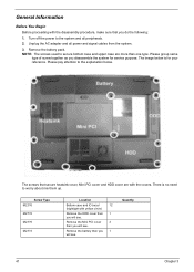
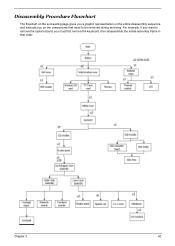
Chapter 3 42 For example, if you want to remove the system board, you on the components that order. Disassembly Procedure Flowchart The flowchart on the succeeding page gives you a graphic representation on the entire disassembly sequence and instructs you must first remove the keyboard, then disassemble the inside assembly frame in that need to be removed during servicing.
Chapter 3 42 For example, if you want to remove the system board, you on the components that order. Disassembly Procedure Flowchart The flowchart on the succeeding page gives you a graphic representation on the entire disassembly sequence and instructs you must first remove the keyboard, then disassemble the inside assembly frame in that need to be removed during servicing.
Aspire 5510 Service Guide
Page 55
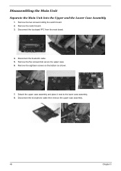
Remove the five screws that secure the upper case. 6. Remove the two screws holding the switch board. 2. Remove the eighteen screws on the bottom as shown. 7. Disconnect the bluetooth cable. 5. Detach the upper case assembly and place it next to the lower case assembly. 8. Remove the switch board. 3. Disconnect the touchpad FFC from the main board. 4. Disconnect the microphone cable then remove the upper case assembly. 49 Chapter 3 Disassembling the Main Unit Separate the Main Unit Into the Upper and the Lower Case Assembly 1.
Remove the five screws that secure the upper case. 6. Remove the two screws holding the switch board. 2. Remove the eighteen screws on the bottom as shown. 7. Disconnect the bluetooth cable. 5. Detach the upper case assembly and place it next to the lower case assembly. 8. Remove the switch board. 3. Disconnect the touchpad FFC from the main board. 4. Disconnect the microphone cable then remove the upper case assembly. 49 Chapter 3 Disassembling the Main Unit Separate the Main Unit Into the Upper and the Lower Case Assembly 1.
Aspire 5510 Service Guide
Page 56
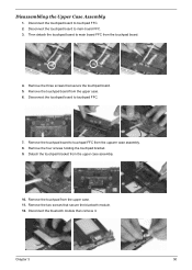
... board FFC from the touchpad board. 4. Chapter 3 50 Remove the four screws holding the touchpad bracket. 9. Remove the two screws that secure the touchpad board. 5. Disassembling the Upper Case Assembly 1. Then detach the touchpad board to touchpad FFC from the upper case. 11. Remove the three screws that secure the bluetooth...
... board FFC from the touchpad board. 4. Chapter 3 50 Remove the four screws holding the touchpad bracket. 9. Remove the two screws that secure the touchpad board. 5. Disassembling the Upper Case Assembly 1. Then detach the touchpad board to touchpad FFC from the upper case. 11. Remove the three screws that secure the bluetooth...
Aspire 5510 Service Guide
Page 57
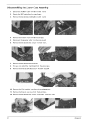
.... 11. Remove the three in one side. 51 Chapter 3 Detach the MDC cable from the main board. 6. Disconnect the speaker cable from the main board. 3. Disassembling the Lower Case Assembly 1. Disconnect the MDC cable from the upper case. 9. Remove the three screws that secure the speaker set on one cover from...
.... 11. Remove the three in one side. 51 Chapter 3 Detach the MDC cable from the main board. 6. Disconnect the speaker cable from the main board. 3. Disassembling the Lower Case Assembly 1. Disconnect the MDC cable from the upper case. 9. Remove the three screws that secure the speaker set on one cover from...
Aspire 5510 Service Guide
Page 59
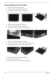
.... 3. Then remove the three screws that secure the left bracket. 53 Chapter 3 Then remove the right bracket. 12. Disconnect the inverter board then remove it. 5. Disassembling the LCD Module 1.
.... 3. Then remove the three screws that secure the left bracket. 53 Chapter 3 Then remove the right bracket. 12. Disconnect the inverter board then remove it. 5. Disassembling the LCD Module 1.
Aspire 5510 Service Guide
Page 61
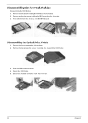
Remove the two screws holding the HDD bracket on one side. 2. Remove another two screws holding the HDD bracket on the other side. 3. Push the ODD holder as the picture shows. 2. Remove the four screws as shown. 4. Disconnect the ODD connector board then remove it. 55 Chapter 3 Then take the hard disc drive out from the HDD bracket. Detach the ODD holder. 5. Disassembling the Optical Drive Module 1. Disassembling the External Modules Disassembling the HDD Module 1. Remove the two screws that secure the optical disc drive and the ODD holder. 3.
Remove the two screws holding the HDD bracket on one side. 2. Remove another two screws holding the HDD bracket on the other side. 3. Push the ODD holder as the picture shows. 2. Remove the four screws as shown. 4. Disconnect the ODD connector board then remove it. 55 Chapter 3 Then take the hard disc drive out from the HDD bracket. Detach the ODD holder. 5. Disassembling the Optical Drive Module 1. Disassembling the External Modules Disassembling the HDD Module 1. Remove the two screws that secure the optical disc drive and the ODD holder. 3.
Aspire 5510 User's Guide
Page 88
... batteries. English 78 8 If an extension cord is 4.6 meters (15 feet). 16 Always disconnect all telephone lines from the wall outlet before serving or disassembling this equipment. 17 Avoid using a telephone (other than a cordless type) during an electrical storm. d If the product does not operate normally when the...-out parts that the total ampere rating of used with the same type as they may expose you to rain or water. Do not disassemble or dispose of them away from children and dispose of the equipment plugged into the product. 10 Do not attempt to normal condition. c...
... batteries. English 78 8 If an extension cord is 4.6 meters (15 feet). 16 Always disconnect all telephone lines from the wall outlet before serving or disassembling this equipment. 17 Avoid using a telephone (other than a cordless type) during an electrical storm. d If the product does not operate normally when the...-out parts that the total ampere rating of used with the same type as they may expose you to rain or water. Do not disassemble or dispose of them away from children and dispose of the equipment plugged into the product. 10 Do not attempt to normal condition. c...
Aspire 5510 User's Guide
Page 89
EVITE EXPONERSE A LOS RAYOS. VARO! The CD or DVD drive's classification label (shown below) is prohibited. Reverse engineering or disassembly is located on the recorded image and does not constitute a malfunction. APPAREIL A LASER DE CLASSE 1 PRODUIT LASERATTENTION: RADIATION DU FAISCEAU LASER INVISIBLE EN CAS D'OUVERTURE. ...
EVITE EXPONERSE A LOS RAYOS. VARO! The CD or DVD drive's classification label (shown below) is prohibited. Reverse engineering or disassembly is located on the recorded image and does not constitute a malfunction. APPAREIL A LASER DE CLASSE 1 PRODUIT LASERATTENTION: RADIATION DU FAISCEAU LASER INVISIBLE EN CAS D'OUVERTURE. ...


