Aspire 5500Z Service Guide
Page 7
Table of Contents Chapter 1 System Specifications 1 Features 1 System Block Diagram 3 Board Layout 4 Top View 4 Bottom View 5 An Aspire tour 7 Front View 7 Closed Front View 8 Left View 9 Right View 9 Rear Panel 10 Bottom Panel 10 Indicators 11 Easy-launch Buttons 12 ... Utility 30 Main 31 Advanced 35 Security 36 Boot 37 Exit 38 BIOS Flash Utility 39 Chapter 3 Machine Disassembly and Replacement 41 General Information 42 Before You Begin 42 Disassembly Procedure Flowchart 43 Removing the Battery Pack 45 Removing the Wireless LAN Card/the HDD Module/the Memory/ the...
Table of Contents Chapter 1 System Specifications 1 Features 1 System Block Diagram 3 Board Layout 4 Top View 4 Bottom View 5 An Aspire tour 7 Front View 7 Closed Front View 8 Left View 9 Right View 9 Rear Panel 10 Bottom Panel 10 Indicators 11 Easy-launch Buttons 12 ... Utility 30 Main 31 Advanced 35 Security 36 Boot 37 Exit 38 BIOS Flash Utility 39 Chapter 3 Machine Disassembly and Replacement 41 General Information 42 Before You Begin 42 Disassembly Procedure Flowchart 43 Removing the Battery Pack 45 Removing the Wireless LAN Card/the HDD Module/the Memory/ the...
Aspire 5500Z Service Guide
Page 49
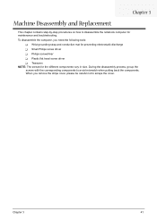
...Tweezers NOTE: The screws for maintenance and troubleshooting. Chapter 3 41 During the disassembly process, group the screws with the corresponding components to avoid mismatch when putting back the components. To disassemble the computer, you remove the stripe cover, please be careful not to scrape ...the cover. Chapter 3 Machine Disassembly and Replacement This chapter contains step-by-step procedures on how to disassemble the notebook computer for the different...
...Tweezers NOTE: The screws for maintenance and troubleshooting. Chapter 3 41 During the disassembly process, group the screws with the corresponding components to avoid mismatch when putting back the components. To disassemble the computer, you remove the stripe cover, please be careful not to scrape ...the cover. Chapter 3 Machine Disassembly and Replacement This chapter contains step-by-step procedures on how to disassemble the notebook computer for the different...
Aspire 5500Z Service Guide
Page 50
General Information Before You Begin Before proceeding with the disassembly procedure, make sure that you do the following: 1. Remove the battery pack. 42 Chapter 3 Turn off the power to the system and all power and signal cables from the system. 3. Unplug the AC adapter and all peripherals. 2.
General Information Before You Begin Before proceeding with the disassembly procedure, make sure that you do the following: 1. Remove the battery pack. 42 Chapter 3 Turn off the power to the system and all power and signal cables from the system. 3. Unplug the AC adapter and all peripherals. 2.
Aspire 5500Z Service Guide
Page 51
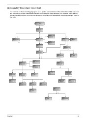
Disassembly Procedure Flowchart The flowchart on the succeeding page gives you a graphic representation on the components that order. Start Battery *2 Middle Cover I*4 Lower Case Assembly *2 Wireless ... CPU Touchpad Bracket Touchpad ODD Module *2 ODD ODD Bracket Chapter 3 43 For example, if you want to remove the system board, you on the entire disassembly sequence and instructs you must first remove the keyboard, then disassemble the inside assembly frame in that need to be removed during servicing.
Disassembly Procedure Flowchart The flowchart on the succeeding page gives you a graphic representation on the components that order. Start Battery *2 Middle Cover I*4 Lower Case Assembly *2 Wireless ... CPU Touchpad Bracket Touchpad ODD Module *2 ODD ODD Bracket Chapter 3 43 For example, if you want to remove the system board, you on the entire disassembly sequence and instructs you must first remove the keyboard, then disassemble the inside assembly frame in that need to be removed during servicing.
Aspire 5500Z Service Guide
Page 58
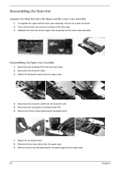
To separate the upper and the lower case assembly, remove six screws as shown. 2. Disassembling the Upper Case Assembly 1. Disconnect the bluetooth cable from the upper case. 9. Remove the three screws fastening the touchpad board. 7. Disconnect the touchpad to ... assembly. Detach the bluetooth module from the main board. 2. Turn over the main unit, remove 9 screws on the other side. 3. Disconnect the bluetooth cable. 3. Disassembling the Main Unit Separate the Main Unit Into the Upper and the Lower Case Assembly 1. Disconnect the touchpad FFC from the upper case. 4.
To separate the upper and the lower case assembly, remove six screws as shown. 2. Disassembling the Upper Case Assembly 1. Disconnect the bluetooth cable from the upper case. 9. Remove the three screws fastening the touchpad board. 7. Disconnect the touchpad to ... assembly. Detach the bluetooth module from the main board. 2. Turn over the main unit, remove 9 screws on the other side. 3. Disconnect the bluetooth cable. 3. Disassembling the Main Unit Separate the Main Unit Into the Upper and the Lower Case Assembly 1. Disconnect the touchpad FFC from the upper case. 4.
Aspire 5500Z Service Guide
Page 59
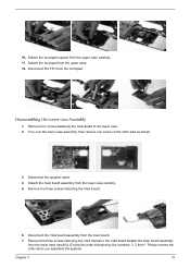
Detach the touchpad support from the lower case carefully. (Follow the order indicated by the numbers: 3, 2 then1. Disassembling the Lower Case Assembly 1. Chapter 3 51 Remove the three screws fastening the VGA themal to the lower case. 2. Turn over the lower case assembly, then ...
Detach the touchpad support from the lower case carefully. (Follow the order indicated by the numbers: 3, 2 then1. Disassembling the Lower Case Assembly 1. Chapter 3 51 Remove the three screws fastening the VGA themal to the lower case. 2. Turn over the lower case assembly, then ...

Aspire 5500Z Service Guide
Page 60
Take out the speaker set to the lower case. 14. Remove the two screws fastening the modem board as shwon. 11. Remove the two screws holding the speaker set from the lower case. Disconnect the modem cable from the modem board. 13. This completes the main unit disassembly. 52 Chapter 3 Disconnect the modem cable from the main board. 10. Disconnect the modem board from the VGA board. 9. Detach the VGA thermal from the main board. 12. 8.
Take out the speaker set to the lower case. 14. Remove the two screws fastening the modem board as shwon. 11. Remove the two screws holding the speaker set from the lower case. Disconnect the modem cable from the modem board. 13. This completes the main unit disassembly. 52 Chapter 3 Disconnect the modem cable from the main board. 10. Disconnect the modem board from the VGA board. 9. Detach the VGA thermal from the main board. 12. 8.

Aspire 5500Z Service Guide
Page 61
... LCD panel. 8. Take out the LCD assembly from the LCD module. 4. Remove the four screws fastening the LCD left bracket then remove it. 9. Chapter 3 53 Disassembling the LCD Module 1. Then remove the LCD right bracket. 11. Remove the four screw caps as shown. 2. Disconnect the LCD cable and disconnect the inverter...
... LCD panel. 8. Take out the LCD assembly from the LCD module. 4. Remove the four screws fastening the LCD left bracket then remove it. 9. Chapter 3 53 Disassembling the LCD Module 1. Then remove the LCD right bracket. 11. Remove the four screw caps as shown. 2. Disconnect the LCD cable and disconnect the inverter...

Aspire 5500Z Service Guide
Page 62
Remove the ODD bracket from the optical disc drive module. 54 Chapter 3 Remove the two screws holding the HDD bracket on one side. 2. Remove the two screws fastening the ODD bracket. 2. Disassembling the ODD Module 1. Then take the hard disc drive out of the HDD bracket. Disassembling the External Modules Disassembling the HDD Module 1. Remove another two screws holding the HDD bracket on the other side. 3.
Remove the ODD bracket from the optical disc drive module. 54 Chapter 3 Remove the two screws holding the HDD bracket on one side. 2. Remove the two screws fastening the ODD bracket. 2. Disassembling the ODD Module 1. Then take the hard disc drive out of the HDD bracket. Disassembling the External Modules Disassembling the HDD Module 1. Remove another two screws holding the HDD bracket on the other side. 3.
Aspire 5500Z User's Guide - EN
Page 84
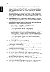
...improper adjustment of other controls may touch dangerous voltage points or short-out parts that could result in a fire or electric shock. Do not disassemble or dispose of them away from lightning. There may expose you to qualified service personnel under the following conditions: a When the power cord...b If liquid has been spilled into the product. 10 Do not attempt to service this product from the wall outlet before serving or disassembling this product through cabinet slots as they may result in damage and will often require extensive work by a qualified technician to restore the ...
...improper adjustment of other controls may touch dangerous voltage points or short-out parts that could result in a fire or electric shock. Do not disassemble or dispose of them away from lightning. There may expose you to qualified service personnel under the following conditions: a When the power cord...b If liquid has been spilled into the product. 10 Do not attempt to service this product from the wall outlet before serving or disassembling this product through cabinet slots as they may result in damage and will often require extensive work by a qualified technician to restore the ...

Aspire 5500Z User's Guide - EN
Page 85
... is produced with this copyright protection technology must be authorized by Macrovision, and is intended for home and other intellectual property rights. Reverse engineering or disassembly is located on the recorded image and does not constitute a malfunction. AVOID EXPOSURE TO BEAM. APPAREIL A LASER DE CLASSE 1 PRODUIT LASERATTENTION: RADIATION DU FAISCEAU LASER...
... is produced with this copyright protection technology must be authorized by Macrovision, and is intended for home and other intellectual property rights. Reverse engineering or disassembly is located on the recorded image and does not constitute a malfunction. AVOID EXPOSURE TO BEAM. APPAREIL A LASER DE CLASSE 1 PRODUIT LASERATTENTION: RADIATION DU FAISCEAU LASER...


