Aspire 5349, 5749, 5749Z Service Guide
Page 5
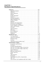
... System 1-5 Platform 1-5 System Memory 1-5 Display 1-5 Audio Subsystem 1-5 Graphics 1-6 Storage Subsystem 1-6 Optical Media Drive 1-6 Privacy Control 1-6 Webcam 1-6 Wireless and networking 1-7 Dimension and Weight 1-7 Power Adapter and Battery 1-7 Input and Controls 1-8 I/O Ports 1-8 Optional Items 1-8 Warranty 1-8 Eco-compliance 1-8 Environment 1-9 Software 1-10 Notebook Tour 1-11 Touchpad Basics 1-18 Using the Keyboard 1-19 Windows Keys 1-20...
... System 1-5 Platform 1-5 System Memory 1-5 Display 1-5 Audio Subsystem 1-5 Graphics 1-6 Storage Subsystem 1-6 Optical Media Drive 1-6 Privacy Control 1-6 Webcam 1-6 Wireless and networking 1-7 Dimension and Weight 1-7 Power Adapter and Battery 1-7 Input and Controls 1-8 I/O Ports 1-8 Optional Items 1-8 Warranty 1-8 Eco-compliance 1-8 Environment 1-9 Software 1-10 Notebook Tour 1-11 Touchpad Basics 1-18 Using the Keyboard 1-19 Windows Keys 1-20...
Aspire 5349, 5749, 5749Z Service Guide
Page 6
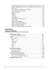
... Supported Resolution (GPU Supported Resolution) 1-32 Mini Card 1-34 3G Card (not available in this model 1-34 Audio Codec and Amplifier 1-35 Audio Interface 1-36 Battery 1-36 VRAM 1-37 USB Port 1-37 AC Adapter 1-37 System Power Management 1-38 Card Reader 1-38 System LED Indicator 1-39 System DMA Specification 1-39 System...
... Supported Resolution (GPU Supported Resolution) 1-32 Mini Card 1-34 3G Card (not available in this model 1-34 Audio Codec and Amplifier 1-35 Audio Interface 1-36 Battery 1-36 VRAM 1-37 USB Port 1-37 AC Adapter 1-37 System Power Management 1-38 Card Reader 1-38 System LED Indicator 1-39 System DMA Specification 1-39 System...
Aspire 5349, 5749, 5749Z Service Guide
Page 7
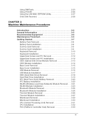
... 2-28 CHAPTER 3 Machine Maintenance Procedures Introduction 3-5 General Information 3-5 Recommended Equipment 3-5 Maintenance Flowchart 3-6 Getting Started 3-7 Battery Pack Removal 3-8 Battery Pack Installation 3-8 Dummy Card Removal 3-9 Dummy Card Installation 3-9 Keyboard Removal 3-10 Keyboard Installation 3-11 UpperCase Screws and... 3-17 HDD (Hard Disk Drive) Removal 3-18 Hard Disk Drive Installation 3-19 RTC (Real Time Clock) Battery Removal 3-20 RTC Battery Installation 3-20 WLAN (Wireless Local Area Network) Module Removal . . . 3-21 WLAN Module Installation 3-23 ...
... 2-28 CHAPTER 3 Machine Maintenance Procedures Introduction 3-5 General Information 3-5 Recommended Equipment 3-5 Maintenance Flowchart 3-6 Getting Started 3-7 Battery Pack Removal 3-8 Battery Pack Installation 3-8 Dummy Card Removal 3-9 Dummy Card Installation 3-9 Keyboard Removal 3-10 Keyboard Installation 3-11 UpperCase Screws and... 3-17 HDD (Hard Disk Drive) Removal 3-18 Hard Disk Drive Installation 3-19 RTC (Real Time Clock) Battery Removal 3-20 RTC Battery Installation 3-20 WLAN (Wireless Local Area Network) Module Removal . . . 3-21 WLAN Module Installation 3-23 ...
Aspire 5349, 5749, 5749Z Service Guide
Page 12
... System 1-5 Platform 1-5 System Memory 1-5 Display 1-5 Audio Subsystem 1-5 Graphics 1-6 Storage Subsystem 1-6 Optical Media Drive 1-6 Privacy Control 1-6 Webcam 1-6 Wireless and networking 1-7 Dimension and Weight 1-7 Power Adapter and Battery 1-7 Input and Controls 1-8 I/O Ports 1-8 Optional Items 1-8 Warranty 1-8 Eco-compliance 1-8 Environment 1-9 Software 1-10 Notebook Tour 1-11 Touchpad Basics 1-18 Using the Keyboard 1-19 Windows Keys 1-20...
... System 1-5 Platform 1-5 System Memory 1-5 Display 1-5 Audio Subsystem 1-5 Graphics 1-6 Storage Subsystem 1-6 Optical Media Drive 1-6 Privacy Control 1-6 Webcam 1-6 Wireless and networking 1-7 Dimension and Weight 1-7 Power Adapter and Battery 1-7 Input and Controls 1-8 I/O Ports 1-8 Optional Items 1-8 Warranty 1-8 Eco-compliance 1-8 Environment 1-9 Software 1-10 Notebook Tour 1-11 Touchpad Basics 1-18 Using the Keyboard 1-19 Windows Keys 1-20...
Aspire 5349, 5749, 5749Z Service Guide
Page 17
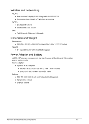
...™ Nplify™ 802.11b/g/n Wi-Fi CERTIFIED™ Supporting Acer SignalUp™ wireless technology WPAN: Bluetooth® 3.0+HS Bluetooth® 2.0/2.1+EDR LAN: Fast Ethernet, Wake...381 (W) x 253 (D) x 29.6/34.7 (H) mm (15 x 9.96 x 1.17/1.37 inches) Weight: 2.4 kg (5.29 lbs.)10 with 6-cell battery pack Power Adapter and Battery 0 ACPI 3.0 CPU power management standard: supports Standby and Hibernation power-saving modes Power adapter: 3-pin 65 W AC adapter: 95...
...™ Nplify™ 802.11b/g/n Wi-Fi CERTIFIED™ Supporting Acer SignalUp™ wireless technology WPAN: Bluetooth® 3.0+HS Bluetooth® 2.0/2.1+EDR LAN: Fast Ethernet, Wake...381 (W) x 253 (D) x 29.6/34.7 (H) mm (15 x 9.96 x 1.17/1.37 inches) Weight: 2.4 kg (5.29 lbs.)10 with 6-cell battery pack Power Adapter and Battery 0 ACPI 3.0 CPU power management standard: supports Standby and Hibernation power-saving modes Power adapter: 3-pin 65 W AC adapter: 95...
Aspire 5349, 5749, 5749Z Service Guide
Page 18
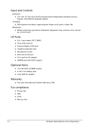
Input and Controls 0 Keyboard 103-/104-/107-key Acer FineTip keyboard with independent standard numeric keypad, international language support Touchpad Multi-gesture touchpad, supporting two-finger scroll, pinch, rotate, flip ...jack for AC adapter HDMI® port with HDCP support Optional Items 0 1/2/4 GB DDR3 soDIMM module 6-cell Li-ion battery pack 3-pin 65W AC adapter Warranty 0 One-year International Travelers Warranty (ITW) Eco-compliance 0 Energy Star &#...
Input and Controls 0 Keyboard 103-/104-/107-key Acer FineTip keyboard with independent standard numeric keypad, international language support Touchpad Multi-gesture touchpad, supporting two-finger scroll, pinch, rotate, flip ...jack for AC adapter HDMI® port with HDCP support Optional Items 0 1/2/4 GB DDR3 soDIMM module 6-cell Li-ion battery pack 3-pin 65W AC adapter Warranty 0 One-year International Travelers Warranty (ITW) Eco-compliance 0 Energy Star &#...

Aspire 5349, 5749, 5749Z Service Guide
Page 22
Fully charged: The light shows blue when in AC mode. 9 Palmrest Comfortable support area for your hands when you use the computer. 10 Speaker Delivers audio output Note: Color option may depend on the model. 1-12 Hardware Specifications and Configurations Top View # Icon Item 8 Power indicator Description Indicates the computer's power status. Charging: The light shows amber when the battery is charging. 2. Table 1-1. Battery indicator Indicates the computer's battery status. 1.
Fully charged: The light shows blue when in AC mode. 9 Palmrest Comfortable support area for your hands when you use the computer. 10 Speaker Delivers audio output Note: Color option may depend on the model. 1-12 Hardware Specifications and Configurations Top View # Icon Item 8 Power indicator Description Indicates the computer's power status. Charging: The light shows amber when the battery is charging. 2. Table 1-1. Battery indicator Indicates the computer's battery status. 1.
Aspire 5349, 5749, 5749Z Service Guide
Page 24
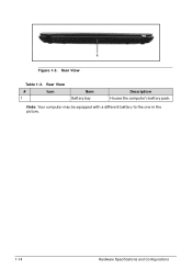
Rear View # Icon 1 Item Battery bay Description Houses the computer's battery pack. Rear View Table 1-3. Note: Your computer may be equipped with a different battery to the one in the picture. 1-14 Hardware Specifications and Configurations Figure 1-3.
Rear View # Icon 1 Item Battery bay Description Houses the computer's battery pack. Rear View Table 1-3. Note: Your computer may be equipped with a different battery to the one in the picture. 1-14 Hardware Specifications and Configurations Figure 1-3.
Aspire 5349, 5749, 5749Z Service Guide
Page 27
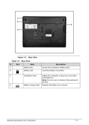
Figure 1-6. Locks the battery in position. 3 Ventilation slots Enable the computer to stay cool, even after prolonged use. Base View Table 1-6. Hardware Specifications and Configurations 1-17 Note: Do not cover or obstruct the opening of the fan. 4 Battery release latch Releases the battery for removal. Base View # Icon Item 1 Battery bay 2 Battery lock Description Houses the computer's battery pack.
Figure 1-6. Locks the battery in position. 3 Ventilation slots Enable the computer to stay cool, even after prolonged use. Base View Table 1-6. Hardware Specifications and Configurations 1-17 Note: Do not cover or obstruct the opening of the fan. 4 Battery release latch Releases the battery for removal. Base View # Icon Item 1 Battery bay 2 Battery lock Description Houses the computer's battery pack.
Aspire 5349, 5749, 5749Z Service Guide
Page 34
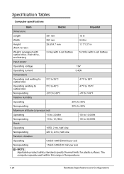
... mm 9.96 in Height (front to rear) 29.6/34.7 mm 1.17/1.37 in Weight (equipped with optical drive, flash drive, and battery) 2.4 kg with 6-cell battery 5.29 lbs with 6-cell battery Input power Operating voltage 19V Operating current 3.42A Temperature Operating (not writing to optical disc) 5°C to 35°C 41°F to...
... mm 9.96 in Height (front to rear) 29.6/34.7 mm 1.17/1.37 in Weight (equipped with optical drive, flash drive, and battery) 2.4 kg with 6-cell battery 5.29 lbs with 6-cell battery Input power Operating voltage 19V Operating current 3.42A Temperature Operating (not writing to optical disc) 5°C to 35°C 41°F to...
Aspire 5349, 5749, 5749Z Service Guide
Page 46
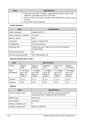
..., up to 300 Mbps for Draft-N b, g, n b, g, n PCI-E PCI-E Realtek RTL8188CE 11-54 Mbps, up to 300 Mbps for Draft-N a, g, n PCI-E Battery Item Vendor & Model name Battery Type Pack capacity Number of battery cell Package configuration Specification Sanyo AS10D31, Sony AS10D41, Panasonic AS10D51, Samsung AS10D61, Simplo AS10D, LGC AS10D Lithium-Ion 4400mAh 6 MSOP-8L...
..., up to 300 Mbps for Draft-N b, g, n b, g, n PCI-E PCI-E Realtek RTL8188CE 11-54 Mbps, up to 300 Mbps for Draft-N a, g, n PCI-E Battery Item Vendor & Model name Battery Type Pack capacity Number of battery cell Package configuration Specification Sanyo AS10D31, Sony AS10D41, Panasonic AS10D51, Samsung AS10D61, Simplo AS10D, LGC AS10D Lithium-Ion 4400mAh 6 MSOP-8L...
Aspire 5349, 5749, 5749Z Service Guide
Page 49
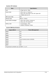
System LED Indicator Item Lock System state HDD access state Wireless state Power button backlight Battery state Specification Caps Lock on = Blue Blue color on: System on Blue color and amber color off: ...: S3 N/A Wifi on = Amber Blue color solid on: System on Blue color off: System off Full charging = Blue Battery charging = Amber System DMA Specification Legacy Mode Power Management DMA0 N/A DMA1 N/A DMA2 N/A DMA3 N/A DMA4 Direct memory access controller DMA5 N/A DMA6 N/A DMA7 N/A *ExpressCard controller...
System LED Indicator Item Lock System state HDD access state Wireless state Power button backlight Battery state Specification Caps Lock on = Blue Blue color on: System on Blue color and amber color off: ...: S3 N/A Wifi on = Amber Blue color solid on: System on Blue color off: System off Full charging = Blue Battery charging = Amber System DMA Specification Legacy Mode Power Management DMA0 N/A DMA1 N/A DMA2 N/A DMA3 N/A DMA4 Direct memory access controller DMA5 N/A DMA6 N/A DMA7 N/A *ExpressCard controller...
Aspire 5349, 5749, 5749Z Service Guide
Page 72
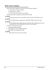
... not available, create one before Flash utility is used . BIOS Flash Utilities 0 BIOS Flash memory updates are required for the following to run Flash. 1. If battery pack does not contain power to bootable USB HDD. 3. Use the Flash utility to update the system BIOS Flash ROM.
... not available, create one before Flash utility is used . BIOS Flash Utilities 0 BIOS Flash memory updates are required for the following to run Flash. 1. If battery pack does not contain power to bootable USB HDD. 3. Use the Flash utility to update the system BIOS Flash ROM.
Aspire 5349, 5749, 5749Z Service Guide
Page 86
Introduction 3-5 General Information 3-5 Recommended Equipment 3-5 Maintenance Flowchart 3-6 Getting Started 3-7 Battery Pack Removal 3-8 Battery Pack Installation 3-8 Dummy Card Removal 3-9 Dummy Card Installation 3-9 Keyboard Removal 3-10 Keyboard Installation 3-11 UpperCase Screws...3-16 USB Module Installation 3-17 HDD (Hard Disk Drive) Removal 3-18 Hard Disk Drive Installation 3-19 RTC (Real Time Clock) Battery Removal 3-20 RTC Battery Installation 3-20 WLAN (Wireless Local Area Network) Module Removal . . . .3-21 WLAN Module Installation 3-23 Bluetooth Module Removal 3-24...
Introduction 3-5 General Information 3-5 Recommended Equipment 3-5 Maintenance Flowchart 3-6 Getting Started 3-7 Battery Pack Removal 3-8 Battery Pack Installation 3-8 Dummy Card Removal 3-9 Dummy Card Installation 3-9 Keyboard Removal 3-10 Keyboard Installation 3-11 UpperCase Screws...3-16 USB Module Installation 3-17 HDD (Hard Disk Drive) Removal 3-18 Hard Disk Drive Installation 3-19 RTC (Real Time Clock) Battery Removal 3-20 RTC Battery Installation 3-20 WLAN (Wireless Local Area Network) Module Removal . . . .3-21 WLAN Module Installation 3-23 Bluetooth Module Removal 3-24...
Aspire 5349, 5749, 5749Z Service Guide
Page 90
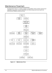
... Flow 3-6 Machine Maintenance Procedures Maintenance Flowchart 0 The flowchart in Jack LCD module Speaker LCD bezel Camera LCD panel LCD hinge LVDS cable Thermal module Figure 3-1. Battery Dummy card Keyboard Speaker cable Power FFC Touchpad FFC ODD module Base cover USB module HDD module WLAN module Bluetooth module Mainboard CPU PCH Lower...
... Flow 3-6 Machine Maintenance Procedures Maintenance Flowchart 0 The flowchart in Jack LCD module Speaker LCD bezel Camera LCD panel LCD hinge LVDS cable Thermal module Figure 3-1. Battery Dummy card Keyboard Speaker cable Power FFC Touchpad FFC ODD module Base cover USB module HDD module WLAN module Bluetooth module Mainboard CPU PCH Lower...
Aspire 5349, 5749, 5749Z Service Guide
Page 92
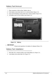
Place computer on flat surface, battery side up. 2. Push battery lock/unlock latch (A) to release position (Figure 3-3). 4. Lift battery pack (C) from battery bay (Figure 3-3). Lock battery lock/unlock latch (A) (Figure 3-3). 3-8 Machine Maintenance Procedures Battery Pack Installation 0 1. C A B Figure 3-3. Battery + IMPORTANT: Follow local regulations for battery (C) disposal (Figure 3-3). Hold latch (B) in release position and install battery (C) (Figure 3-3). 2. Push and hold battery release latch (B) to unlock position (Figure 3-3). 3. Battery Pack Removal 0 1.
Place computer on flat surface, battery side up. 2. Push battery lock/unlock latch (A) to release position (Figure 3-3). 4. Lift battery pack (C) from battery bay (Figure 3-3). Lock battery lock/unlock latch (A) (Figure 3-3). 3-8 Machine Maintenance Procedures Battery Pack Installation 0 1. C A B Figure 3-3. Battery + IMPORTANT: Follow local regulations for battery (C) disposal (Figure 3-3). Hold latch (B) in release position and install battery (C) (Figure 3-3). 2. Push and hold battery release latch (B) to unlock position (Figure 3-3). 3. Battery Pack Removal 0 1.
Aspire 5349, 5749, 5749Z Service Guide
Page 94
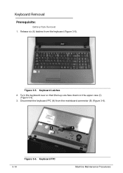
Keyboard FPC Machine Maintenance Procedures Keyboard Latches 2. Turn the keyboard over so that the keys are face down on the upper case (C) (Figure 3-6). 3. Figure 3-5. B A C 3-10 Figure 3-6. Keyboard Removal 0 Prerequisite: Battery Pack Removal 1. Disconnect the keyboard FPC (A) from the keyboard (Figure 3-5). Release six (6) latches from the mainboard connector (B) (Figure 3-6).
Keyboard FPC Machine Maintenance Procedures Keyboard Latches 2. Turn the keyboard over so that the keys are face down on the upper case (C) (Figure 3-6). 3. Figure 3-5. B A C 3-10 Figure 3-6. Keyboard Removal 0 Prerequisite: Battery Pack Removal 1. Disconnect the keyboard FPC (A) from the keyboard (Figure 3-5). Release six (6) latches from the mainboard connector (B) (Figure 3-6).
Aspire 5349, 5749, 5749Z Service Guide
Page 95
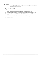
Keyboard Installation 0 1. Refer to Figure 3-5. 5. Press down on the upper cover. Refer to Figure 3-6. 2. ! Machine Maintenance Procedures 3-11 Turn the keyboard over and align the keyboard with the indentation in the upper cover. 4. Install the battery. Refer to the mainboard connector (B). CAUTION: Keyboard FPC (Flexible Printed Circuit) can be damaged if removed while the mainboard connector is locked. Put the keyboard face down to secure the latches on the upper case (C). Connect the keyboard FPC (A) to Figure 3-6. 3.
Keyboard Installation 0 1. Refer to Figure 3-5. 5. Press down on the upper cover. Refer to Figure 3-6. 2. ! Machine Maintenance Procedures 3-11 Turn the keyboard over and align the keyboard with the indentation in the upper cover. 4. Install the battery. Refer to the mainboard connector (B). CAUTION: Keyboard FPC (Flexible Printed Circuit) can be damaged if removed while the mainboard connector is locked. Put the keyboard face down to secure the latches on the upper case (C). Connect the keyboard FPC (A) to Figure 3-6. 3.

Aspire 5349, 5749, 5749Z Service Guide
Page 97
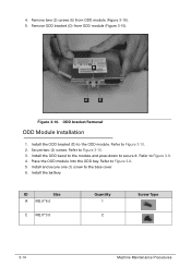
B A Figure 3-8. ODD Module in Lower Cover 2. Remove one (1) screw (A) from ODD module (Figure 3-9). Remove ODD bezel (C) from lower cover (Figure 3-8). C Figure 3-9. Remove ODD module from ODD bay (B) (Figure 3-8). 3. ODD bezel Removal Machine Maintenance Procedures 3-13 ODD (Optical Disk Drive) Module Removal 0 Prerequisite: Battery Pack Removal 1.
B A Figure 3-8. ODD Module in Lower Cover 2. Remove one (1) screw (A) from ODD module (Figure 3-9). Remove ODD bezel (C) from lower cover (Figure 3-8). C Figure 3-9. Remove ODD module from ODD bay (B) (Figure 3-8). 3. ODD bezel Removal Machine Maintenance Procedures 3-13 ODD (Optical Disk Drive) Module Removal 0 Prerequisite: Battery Pack Removal 1.
Aspire 5349, 5749, 5749Z Service Guide
Page 98
... down to Figure 3-10. 2. Refer to secure it. D E E Figure 3-10. Refer to the ODD module. Place the ODD module into the ODD bay. Install the battery. ID Size A M2.5*6.0 E M2.0*3.0 Quantity 1 2 Screw Type 3-14 Machine Maintenance Procedures Remove ODD bracket (D) from ODD module (Figure 3-10). 5. Install the ODD bracket (D) to Figure...
... down to Figure 3-10. 2. Refer to secure it. D E E Figure 3-10. Refer to the ODD module. Place the ODD module into the ODD bay. Install the battery. ID Size A M2.5*6.0 E M2.0*3.0 Quantity 1 2 Screw Type 3-14 Machine Maintenance Procedures Remove ODD bracket (D) from ODD module (Figure 3-10). 5. Install the ODD bracket (D) to Figure...


