Aspire 5349, 5749, 5749Z Service Guide
Page 7
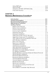
... UpperCase Screws and FFC Installation 3-12 ODD (Optical Disk Drive) Module Removal 3-13 ODD Module Installation 3-14 Base Cover Removal 3-15 Base Cover Installation 3-15 USB Module Removal 3-16 USB Module Installation 3-17 HDD (Hard Disk Drive) Removal 3-18 Hard Disk Drive Installation 3-19 RTC (Real Time Clock) Battery Removal 3-20 RTC Battery Installation 3-20 WLAN (Wireless Local Area Network...
... UpperCase Screws and FFC Installation 3-12 ODD (Optical Disk Drive) Module Removal 3-13 ODD Module Installation 3-14 Base Cover Removal 3-15 Base Cover Installation 3-15 USB Module Removal 3-16 USB Module Installation 3-17 HDD (Hard Disk Drive) Removal 3-18 Hard Disk Drive Installation 3-19 RTC (Real Time Clock) Battery Removal 3-20 RTC Battery Installation 3-20 WLAN (Wireless Local Area Network...
Aspire 5349, 5749, 5749Z Service Guide
Page 86
... UpperCase Screws and FFC Installation 3-12 ODD (Optical Disk Drive) Module Removal 3-13 ODD Module Installation 3-14 Base Cover Removal 3-15 Base Cover Installation 3-15 USB Module Removal 3-16 USB Module Installation 3-17 HDD (Hard Disk Drive) Removal 3-18 Hard Disk Drive Installation 3-19 RTC (Real Time Clock) Battery Removal 3-20 RTC Battery Installation 3-20 WLAN (Wireless Local Area Network...
... UpperCase Screws and FFC Installation 3-12 ODD (Optical Disk Drive) Module Removal 3-13 ODD Module Installation 3-14 Base Cover Removal 3-15 Base Cover Installation 3-15 USB Module Removal 3-16 USB Module Installation 3-17 HDD (Hard Disk Drive) Removal 3-18 Hard Disk Drive Installation 3-19 RTC (Real Time Clock) Battery Removal 3-20 RTC Battery Installation 3-20 WLAN (Wireless Local Area Network...
Aspire 5349, 5749, 5749Z Service Guide
Page 102
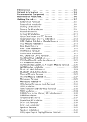
Using the pull-tab, slide the HDD module in Figure 3-15. 3-18 Figure 3-15. Remove the HDD module as shown in the direction of the arrow to disconnect the interface. (Figure 3-14). Figure 3-14. HDD Location 2. HDD Removal Machine Maintenance Procedures HDD (Hard Disk Drive) Removal 0 Prerequisite: USB Module Removal 1.
Using the pull-tab, slide the HDD module in Figure 3-15. 3-18 Figure 3-15. Remove the HDD module as shown in the direction of the arrow to disconnect the interface. (Figure 3-14). Figure 3-14. HDD Location 2. HDD Removal Machine Maintenance Procedures HDD (Hard Disk Drive) Removal 0 Prerequisite: USB Module Removal 1.
Aspire 5349, 5749, 5749Z Service Guide
Page 103
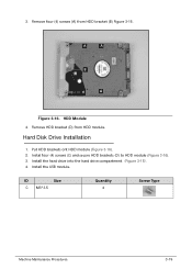
Put HDD brackets ont HDD module (Figure 3-16). 2. Install the hard drive into the hard drive compartment. (Figure 3-15). 4. Install the USB module. Remove four (4) screws (A) from HDD module. Remove HDD bracket (D) from HDD bracket (B) Figure 3-15. HDD Module 4. Instal four (4) screws (C) and secure HDD brackets (D) to HDD module (Figure 3-16). 3. A A B A A Figure 3-16. 3. ID Size C M3*3.5 Quantity 4 Screw Type Machine Maintenance Procedures 3-19 Hard Disk Drive Installation 0 1.
Put HDD brackets ont HDD module (Figure 3-16). 2. Install the hard drive into the hard drive compartment. (Figure 3-15). 4. Install the USB module. Remove four (4) screws (A) from HDD module. Remove HDD bracket (D) from HDD bracket (B) Figure 3-15. HDD Module 4. Instal four (4) screws (C) and secure HDD brackets (D) to HDD module (Figure 3-16). 3. A A B A A Figure 3-16. 3. ID Size C M3*3.5 Quantity 4 Screw Type Machine Maintenance Procedures 3-19 Hard Disk Drive Installation 0 1.
Aspire 5349, 5749, 5749Z Service Guide
Page 152
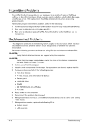
...NOTE: NOTE: Verify that there are supported by a variety of reasons that all of the failure is detected, replace the FRU. Remove or disconnect all attached devices are no error is inoperative. Visually check components for the system board in loop mode at least 10... problem exists. Perform the following devices: Non-Acer devices Printer, mouse, and other external devices Battery pack Hard disk drive DIMM CD-ROM/Diskette drive Module PC Cards 4. NOTE: NOTE: Verify...
...NOTE: NOTE: Verify that there are supported by a variety of reasons that all of the failure is detected, replace the FRU. Remove or disconnect all attached devices are no error is inoperative. Visually check components for the system board in loop mode at least 10... problem exists. Perform the following devices: Non-Acer devices Printer, mouse, and other external devices Battery pack Hard disk drive DIMM CD-ROM/Diskette drive Module PC Cards 4. NOTE: NOTE: Verify...


