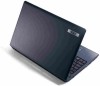
Aspire 5349, 5749, 5749Z Service Guide
Page 5
... Windows Keys 1-20 Hotkeys 1-21 Using the communication key 1-22 Specification Tables 1-24 Computer specifications 1-24 Processor 1-25 Processor Specifications 1-26 CPU Fan True Value Table (TJ100-CPU 1-26 CPU Fan True Value Table (TJ85-CPU 1-27 System Memory 1-27 Memory Combinations 1-28 Video Interface 1-28 BIOS 1-28 LAN Interface 1-29 Keyboard...
Aspire 5349, 5749, 5749Z Service Guide
Page 12
... Windows Keys 1-20 Hotkeys 1-21 Using the communication key 1-22 Specification Tables 1-24 Computer specifications 1-24 Processor 1-25 Processor Specifications 1-26 CPU Fan True Value Table (TJ100-CPU 1-26 CPU Fan True Value Table (TJ85-CPU 1-27 System Memory 1-27 Memory Combinations 1-28 Video Interface 1-28 BIOS 1-28 LAN Interface 1-29 Keyboard...
Aspire 5349, 5749, 5749Z Service Guide
Page 27
Note: Do not cover or obstruct the opening of the fan. 4 Battery release latch Releases the battery for removal. Figure 1-6. Base View # Icon Item 1 Battery bay 2 Battery lock Description Houses the computer's battery pack. Locks the battery in position. 3 Ventilation slots Enable the computer to stay cool, even after prolonged use. Base View Table 1-6. Hardware Specifications and Configurations 1-17
Aspire 5349, 5749, 5749Z Service Guide
Page 33
... ATHEROS AR8158 10/100 LAN P18 X'TAL 25MHz P16 P16 P17 RJ45 P18 1-23 HP Jack MIC Jack SPK DMIC SPI ROM Touch Pad Keyboard Fan Driver P22 P22 P21 P21 P26 P25 P25 (DA Type) P25 SODIMM 0 DDR III - System Block Diagram Hardware Specifications and Configurations BLOCK DIAGRAM intel DDR...
Aspire 5349, 5749, 5749Z Service Guide
Page 36
... 2MB L3 rPGA988B Voltage 1.05V~ 1.1V 1.05V~ 1.1V 1.05V~ 1.1V 1.05V~ 1.1V 1.05V~ 1.1V 1.05V~ 1.1V 1.05V~ 1.1V 1.05V~ 1.1V CPU Fan True Value Table (TJ100-CPU) Fan On (°C) Fan Off (°C) 45 40 58 52 70 64 80 75 92 85 Throttling 50%: On =98C ; Off=95C OS Shut...
Aspire 5349, 5749, 5749Z Service Guide
Page 37
... 40 58 52 70 64 78 74 82 80 Throttling 50%: On =83C ; Off=81C OS Shut down: 85C H/W Shut down : 85C Fan Speed (RPM) 3150 3500 3850 4200 N/A System Memory Item Specification Memory controller Built in at CPU Memory size DDR3 1066MHz 1 GB, 2 GB, 4 GB DIMM socket...
Aspire 5349, 5749, 5749Z Service Guide
Page 110
Thermal Module 3-26 Machine Maintenance Procedures Thermal Module Removal 0 Prerequisite: Base Cover Removal 1. Disconnect the thermal fan cable (A) from the thermal module (Figure 3-25). A B Figure 3-25. Remove four (4) screws from the mainboard connector (B) (Figure 3-25). 2.
Aspire 5349, 5749, 5749Z Service Guide
Page 140
..., perform the following . 1. Remove all surge protectors between the computer and the outlet. 3. If the Issue is properly connected to check the thermal unit and fan airways are not necessary to boot the computer to Online Support Information. 4-4 Troubleshooting Power On Issue Computer Shuts Down Intermittently 0 If the system powers off...
Aspire 5349, 5749, 5749Z Service Guide
Page 141
... power by pressing Fn+F5. No Display Issue No POST or Video 0 If the POST or video does not appear, perform the following : Fans start up Status LEDs illuminate If no power, refer to Power On Issues. 3. Hold the power button for specific model procedures. 2. Troubleshooting 4-5 Check...
Aspire 5349, 5749, 5749Z Service Guide
Page 164
Mainboard Bottom Item Description 8 Battery Connector 9 DC Connector 10 LVDS Connector 11 Fan Connector 12 CRT Connector 13 LAN Connector 14 HDMI Connector 15 MINI Card Connector Item 16 17 18 19 20 21 22 Description USB Connector Microphone Connector Headphone Connector Bluetooth Connector USB Connector HDD Connector ODD Connector 5-4 Jumper and Connector Locations 8 9 10 11 22 12 13 14 21 15 16 20 19 18 17 Figure 5-2. Mainboard Bottom Table 5-2.