

Service Guide
Page 7
...and embedded numeric keypad 12 Windows Keys 13 Hot Keys 14 Special Key 15 Using the System Utilities 16 Acer GridVista (dual-display compatible 16 Hardware Specifications and Configurations 18 System Utilities 29 BIOS Setup Utility 29 Navigating the... HDD/BIOS Password Utilities 45 Miscellaneous Utilities 48 Machine Disassembly and Replacement 51 Disassembly Requirements 51 General Information 52 Pre-disassembly Instructions 52 Disassembly Process 52 External Module Disassembly Process 53 External Modules Disassembly Flowchart 53 Removing the Battery Pack 54 Removing the ...
...and embedded numeric keypad 12 Windows Keys 13 Hot Keys 14 Special Key 15 Using the System Utilities 16 Acer GridVista (dual-display compatible 16 Hardware Specifications and Configurations 18 System Utilities 29 BIOS Setup Utility 29 Navigating the... HDD/BIOS Password Utilities 45 Miscellaneous Utilities 48 Machine Disassembly and Replacement 51 Disassembly Requirements 51 General Information 52 Pre-disassembly Instructions 52 Disassembly Process 52 External Module Disassembly Process 53 External Modules Disassembly Flowchart 53 Removing the Battery Pack 54 Removing the ...

Service Guide
Page 8
Table of Contents Main Unit Disassembly Flowchart 65 Removing the Hinge Covers 67 Removing the Switch Cover 68 Removing the Keyboard 70 Removing the Function Board 71 Removing the Speaker Module ... Module 92 Removing the Mainboard 93 Removing the RJ-11 Port 95 Removing the Thermal Module 97 Removing the CPU 99 LCD Module Disassembly Process 100 LCD Module Disassembly Flowchart 100 Removing the LCD Bezel 101 Removing the Camera Module 103 Removing the LCD Panel 104 Removing the LCD Brackets and FPC...
Table of Contents Main Unit Disassembly Flowchart 65 Removing the Hinge Covers 67 Removing the Switch Cover 68 Removing the Keyboard 70 Removing the Function Board 71 Removing the Speaker Module ... Module 92 Removing the Mainboard 93 Removing the RJ-11 Port 95 Removing the Thermal Module 97 Removing the CPU 99 LCD Module Disassembly Process 100 LCD Module Disassembly Flowchart 100 Removing the LCD Bezel 101 Removing the Camera Module 103 Removing the LCD Panel 104 Removing the LCD Brackets and FPC...

Service Guide
Page 61
... Replacement This chapter contains step-by-step procedures on how to avoid mismatch when putting back the components. Disassembly Requirements To disassemble the computer, you need the following tools: • Wrist grounding strap and conductive mat for preventing electrostatic discharge • Flat screwdriver • Philips screwdriver • ...
... Replacement This chapter contains step-by-step procedures on how to avoid mismatch when putting back the components. Disassembly Requirements To disassemble the computer, you need the following tools: • Wrist grounding strap and conductive mat for preventing electrostatic discharge • Flat screwdriver • Philips screwdriver • ...

Service Guide
Page 62
... to any of the hardware components. Place the system on a flat, stable surface. 4. Disassembly Process The disassembly process is divided into the following : 1. Unplug the AC adapter and all peripherals. 2. Remove the battery pack. Main Screw List Description Quantity Acer P/N M2.0D 3.0L K4.6D 0.8T ZK 17 86.AD302.001 M2.5D...
... to any of the hardware components. Place the system on a flat, stable surface. 4. Disassembly Process The disassembly process is divided into the following : 1. Unplug the AC adapter and all peripherals. 2. Remove the battery pack. Main Screw List Description Quantity Acer P/N M2.0D 3.0L K4.6D 0.8T ZK 17 86.AD302.001 M2.5D...

Service Guide
Page 63
For example, if you want to remove the main board, you on the entire disassembly sequence and instructs you must first remove the keyboard, then disassemble the inside assembly frame in that need to be removed during servicing. Turn off system and peripherals power Disconnect power and signal cables from ...Screw M2*3 M3*3 M2.5*5 M2*3 Quantity 2 4 1 2 Part No. 86.AD302.001 86.AD302.005 86.AD302.003 86.AD302.001 Chapter 3 53 External Module Disassembly Process External Modules Disassembly Flowchart The flowchart below gives you a graphic representation on the components that order.
For example, if you want to remove the main board, you on the entire disassembly sequence and instructs you must first remove the keyboard, then disassemble the inside assembly frame in that need to be removed during servicing. Turn off system and peripherals power Disconnect power and signal cables from ...Screw M2*3 M3*3 M2.5*5 M2*3 Quantity 2 4 1 2 Part No. 86.AD302.001 86.AD302.005 86.AD302.003 86.AD302.001 Chapter 3 53 External Module Disassembly Process External Modules Disassembly Flowchart The flowchart below gives you a graphic representation on the components that order.

Service Guide
Page 75
Main Unit Disassembly Process Main Unit Disassembly Flowchart Remove External Modules before proceeding Rem ove Hinge Covers Rem ove Switch Cover Rem ove Keyboard Rem ove Function Board Rem ove Speaker Module ...
Main Unit Disassembly Process Main Unit Disassembly Flowchart Remove External Modules before proceeding Rem ove Hinge Covers Rem ove Switch Cover Rem ove Keyboard Rem ove Function Board Rem ove Speaker Module ...

Service Guide
Page 157
... by removing the power cable and battery and holding down the power button for specific model procedures. 2. If the Issue is still not resolved, see "Disassembly Process" on page 52). 8. Do not replace a non-defective FRUs: No POST or Video If the POST or video doesn't display, perform the following actions...
... by removing the power cable and battery and holding down the power button for specific model procedures. 2. If the Issue is still not resolved, see "Disassembly Process" on page 52). 8. Do not replace a non-defective FRUs: No POST or Video If the POST or video doesn't display, perform the following actions...
Service Guide
Page 158
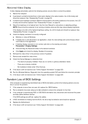
.... 4. Reboot the computer. 2. If extensive pixel damage is still not resolved, see "Online Support Information" on adjusting settings. See "Disassembly Process" on the screen), the LCD is experiencing intermittent loss of BIOS Settings If the computer is faulty and should be replaced. 5. ... the BIOS settings are no red Xs or yellow exclamation marks. • There are still lost, replace the cables. 4. See "Disassembly Process" on the desktop and select Personalize´ Display Settings. If display size is properly installed. If desktop display resolution is not ...
.... 4. Reboot the computer. 2. If extensive pixel damage is still not resolved, see "Online Support Information" on adjusting settings. See "Disassembly Process" on the screen), the LCD is experiencing intermittent loss of BIOS Settings If the computer is faulty and should be replaced. 5. ... the BIOS settings are no red Xs or yellow exclamation marks. • There are still lost, replace the cables. 4. See "Disassembly Process" on the desktop and select Personalize´ Display Settings. If display size is properly installed. If desktop display resolution is not ...
Service Guide
Page 163
... devices. 2. Click Next. i. If the issue is discovered, follow the onscreen information to ensure the computer is set correctly. 7. e. b. Run the Windows Disk Defragmenter. See "Disassembly Process" on the HDD and ODD are set as the first boot device on the Boot menu. 6. Restart the computer and press F2 to locate...
... devices. 2. Click Next. i. If the issue is discovered, follow the onscreen information to ensure the computer is set correctly. 7. e. b. Run the Windows Disk Defragmenter. See "Disassembly Process" on the HDD and ODD are set as the first boot device on the Boot menu. 6. Restart the computer and press F2 to locate...

Service Guide
Page 166
...motherboard, and cable connections. If the drive works with the new cable, the original cable should be replaced. 4. See "Disassembly Process" on page 52. Try an alternate cable, if available. See "Disassembly Process" on page 52. 156 Chapter 4 Listen to the ODD. Click Properties and select the Advanced Settings tab. Remove and...replaced. 3. Check for the other discs. Turn off the power and remove the cover to inspect the connections to enter the BIOS Utility. 2. See "Disassembly Process" on page 52. Test the drive using other ATA Devices shown if applicable. See...
...motherboard, and cable connections. If the drive works with the new cable, the original cable should be replaced. 4. See "Disassembly Process" on page 52. Try an alternate cable, if available. See "Disassembly Process" on page 52. 156 Chapter 4 Listen to the ODD. Click Properties and select the Advanced Settings tab. Remove and...replaced. 3. Check for the other discs. Turn off the power and remove the cover to inspect the connections to enter the BIOS Utility. 2. See "Disassembly Process" on page 52. Test the drive using other ATA Devices shown if applicable. See...

Service Guide
Page 241
... indicator 10 Common Problems 146 computer on indicator 10 CPU 99 D DIMM Module 60 Display 4 display hotkeys 14 E EasyTouch Failure 159 Euro 15 External Module Disassembly Flowchart 53 Index F Features 1 Fingerprint Reader Failure 160 Flash Utility 42 FPC Cable 106 FRU (Field Replaceable Unit) List 173 H Hard Disk Drive Module 61... 150 J Jumper and Connector Locations 169 Top View 169 K Keyboard 70 Keyboard Failure 149 L LCD Bezel 101 LCD Brackets 106 LCD Failure 149 LCD Module Disassembly Flowchart 100 LCD Panel 104 lower cover 57 M Main Unit...
... indicator 10 Common Problems 146 computer on indicator 10 CPU 99 D DIMM Module 60 Display 4 display hotkeys 14 E EasyTouch Failure 159 Euro 15 External Module Disassembly Flowchart 53 Index F Features 1 Fingerprint Reader Failure 160 Flash Utility 42 FPC Cable 106 FRU (Field Replaceable Unit) List 173 H Hard Disk Drive Module 61... 150 J Jumper and Connector Locations 169 Top View 169 K Keyboard 70 Keyboard Failure 149 L LCD Bezel 101 LCD Brackets 106 LCD Failure 149 LCD Module Disassembly Flowchart 100 LCD Panel 104 lower cover 57 M Main Unit...


