Aspire 4735ZG/4935/4935G Quick Guide
Page 3
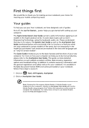
... the screen to complete the installation. For more productive, please refer to the AcerSystem User Guide. 3 First things first We would like to thank you for making an Acer notebook your choice for your notebook. poster helps you get started with language such as system utilities, data recovery, expansion options and troubleshooting. Follow the instructions on how to use your Acer notebook, we have designed a set of the series...
... the screen to complete the installation. For more productive, please refer to the AcerSystem User Guide. 3 First things first We would like to thank you for making an Acer notebook your choice for your notebook. poster helps you get started with language such as system utilities, data recovery, expansion options and troubleshooting. Follow the instructions on how to use your Acer notebook, we have designed a set of the series...

Aspire 4735ZG/4935/4935G Quick Guide
Page 11
... Eye webcam* • Acer PureZone technology* • Optional Acer Xpress VoIP phone* • WLAN: • Intel® Wireless WiFi Link 5100/5300* • Wi-Fi®/WiMAX™: • Intel® Wireless WiFi Link 5150/5350* • WPAN: Bluetooth® 2.0+Enhanced Data Rate (EDR)* • LAN: Gigabit Ethernet; Wake-on -Ring ready • Acer Bio-Protection fingerprint solution* • BIOS user, supervisor, HDD passwords • Kensington lock slot...
... Eye webcam* • Acer PureZone technology* • Optional Acer Xpress VoIP phone* • WLAN: • Intel® Wireless WiFi Link 5100/5300* • Wi-Fi®/WiMAX™: • Intel® Wireless WiFi Link 5150/5350* • WPAN: Bluetooth® 2.0+Enhanced Data Rate (EDR)* • LAN: Gigabit Ethernet; Wake-on -Ring ready • Acer Bio-Protection fingerprint solution* • BIOS user, supervisor, HDD passwords • Kensington lock slot...

Service Guide
Page 7
... Buttons 10 Touchpad Basics (with fingerprint reader 11 Using the Keyboard 12 Lock Keys and embedded numeric keypad 12 Windows Keys 13 Hot Keys 14 Special Key 15 Using the System Utilities 16 Acer GridVista (dual-display compatible 16 Hardware Specifications and Configurations 18 System Utilities 29 BIOS Setup Utility 29 Navigating the BIOS Utility 29 Information 30 Main 31 Advanced 32 Security 35 Power 38 Boot 40 Exit 41 BIOS Flash Utilities 42 DOS Flash Utility 43 WinFlash Utility 44 Remove HDD/BIOS Password Utilities 45 Miscellaneous Utilities...
... Buttons 10 Touchpad Basics (with fingerprint reader 11 Using the Keyboard 12 Lock Keys and embedded numeric keypad 12 Windows Keys 13 Hot Keys 14 Special Key 15 Using the System Utilities 16 Acer GridVista (dual-display compatible 16 Hardware Specifications and Configurations 18 System Utilities 29 BIOS Setup Utility 29 Navigating the BIOS Utility 29 Information 30 Main 31 Advanced 32 Security 35 Power 38 Boot 40 Exit 41 BIOS Flash Utilities 42 DOS Flash Utility 43 WinFlash Utility 44 Remove HDD/BIOS Password Utilities 45 Miscellaneous Utilities...

Service Guide
Page 8
... Removing the Switch Cover 68 Removing the Keyboard 70 Removing the Function Board 71 Removing the Speaker Module 72 Removing the LCD Module 74 Removing the Upper Base 79 Removing the Finger Print Reader 82 Removing the TouchPad Bracket 84 Removing the eKey Board 86 Removing the Media Board 87 Removing the USB Board 89 Removing the Modem Module 91 Removing the Bluetooth Module 92 Removing the Mainboard 93 Removing the RJ-11 Port 95 Removing the Thermal Module 97 Removing the CPU 99 LCD Module Disassembly Process 100 LCD Module Disassembly Flowchart 100 Removing...
... Removing the Switch Cover 68 Removing the Keyboard 70 Removing the Function Board 71 Removing the Speaker Module 72 Removing the LCD Module 74 Removing the Upper Base 79 Removing the Finger Print Reader 82 Removing the TouchPad Bracket 84 Removing the eKey Board 86 Removing the Media Board 87 Removing the USB Board 89 Removing the Modem Module 91 Removing the Bluetooth Module 92 Removing the Mainboard 93 Removing the RJ-11 Port 95 Removing the Thermal Module 97 Removing the CPU 99 LCD Module Disassembly Process 100 LCD Module Disassembly Flowchart 100 Removing...
Service Guide
Page 9
... Contents Troubleshooting 145 Common Problems 145 Power On Issue 146 No Display Issue 147 Random Loss of BIOS Settings 148 LCD Failure 149 Built-In Keyboard Failure 149 Touchpad Failure 150 Internal Speaker Failure 150 Internal Microphone Failure 152 HDD Not Operating Correctly 153 ODD Failure 154 USB Failure (Rightside 157 Modem Function Failure 157 Wireless Function Failure 158 Bluetooth Function Failure 158 EasyTouch Button Failure 159 Media Board Failure 159 Fingerprint Reader Failure...
... Contents Troubleshooting 145 Common Problems 145 Power On Issue 146 No Display Issue 147 Random Loss of BIOS Settings 148 LCD Failure 149 Built-In Keyboard Failure 149 Touchpad Failure 150 Internal Speaker Failure 150 Internal Microphone Failure 152 HDD Not Operating Correctly 153 ODD Failure 154 USB Failure (Rightside 157 Modem Function Failure 157 Wireless Function Failure 158 Bluetooth Function Failure 158 EasyTouch Button Failure 159 Media Board Failure 159 Fingerprint Reader Failure...

Service Guide
Page 20
Indicates when the hard disk drive is activated. Lights up when Num Lock is charging. 2. Fully charged: The light shows green when in AC mode. They are application buttons. Launch Acer Empowering Technology. (user-programmable) 10 Chapter 1 Icon Function Power Description Indicates the computer's power status. Lights up when Caps Lock is active. NOTE: 1. Charging: The battery light shows amber when the battery is activated. To set to -read status indicators: The front panel indicators are visible even when the computer...
Indicates when the hard disk drive is activated. Lights up when Num Lock is charging. 2. Fully charged: The light shows green when in AC mode. They are application buttons. Launch Acer Empowering Technology. (user-programmable) 10 Chapter 1 Icon Function Power Description Indicates the computer's power status. Lights up when Caps Lock is active. NOTE: 1. Charging: The battery light shows amber when the battery is activated. To set to -read status indicators: The front panel indicators are visible even when the computer...
Service Guide
Page 40
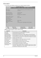
... 2 Displays system BIOS version. This field displays the serial number of HDD installed on primary IDE master. InsydeH20 Setup Utility Information Main Advanced Security Power Boot Exit Rev 3.5 CPU Type: CPU Speed: Intel(R) Core(tm)2 Duo CPU P7350 @ 2.00 GHz 2.00 GHz HDD Model Name: HDD Serial Number: ATAPI Model Name: ST9160310AS 5SV06JJS Slimtype DVD A DS8A2S System BIOS Version: VGA BIOS Version: Serial Number: Asset Tag Number: Product Name: Manufacturer Name: UUID: V0.09 Intel V1659 Aspire 4935 Acer 21401492...
... 2 Displays system BIOS version. This field displays the serial number of HDD installed on primary IDE master. InsydeH20 Setup Utility Information Main Advanced Security Power Boot Exit Rev 3.5 CPU Type: CPU Speed: Intel(R) Core(tm)2 Duo CPU P7350 @ 2.00 GHz 2.00 GHz HDD Model Name: HDD Serial Number: ATAPI Model Name: ST9160310AS 5SV06JJS Slimtype DVD A DS8A2S System BIOS Version: VGA BIOS Version: Serial Number: Asset Tag Number: Product Name: Manufacturer Name: UUID: V0.09 Intel V1659 Aspire 4935 Acer 21401492...

Service Guide
Page 41
... video Memory size. Enables or disables the Press to factory defaults. Settings in boldface are displayed with 24hour format. The hours are the default and suggested parameter settings. Sets the system date. This field reports the total memory size. Memory size is for the hour field. The function allows the user to create a hidden partition on hard disc drive to store operation system and restore the system to display boot menu message during startup. Control the mode in this screen...
... video Memory size. Enables or disables the Press to factory defaults. Settings in boldface are displayed with 24hour format. The hours are the default and suggested parameter settings. Sets the system date. This field reports the total memory size. Memory size is for the hour field. The function allows the user to create a hidden partition on hard disc drive to store operation system and restore the system to display boot menu message during startup. Control the mode in this screen...
Service Guide
Page 45
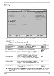
... Password Set User Password Set Hdd Password Rev 3.5 Exit Item Specific Help Install or Change the password and the length of parameters. Settings in this password protects the BIOS Setup Utility from unauthorized access. NOTE: The following sub-options are prompted to enter a password, you have to return your notebook computer to reset it. Press Enter to set the user password. The user can enter Setup menu only and cannot change the value of password must be grayed out if the user password was used...
... Password Set User Password Set Hdd Password Rev 3.5 Exit Item Specific Help Install or Change the password and the length of parameters. Settings in this password protects the BIOS Setup Utility from unauthorized access. NOTE: The following sub-options are prompted to enter a password, you have to return your notebook computer to reset it. Press Enter to set the user password. The user can enter Setup menu only and cannot change the value of password must be grayed out if the user password was used...

Service Guide
Page 46
... to enable the Password on the screen. 3. After setting the password, the computer sets the User Password parameter to highlight the Set Supervisor Password parameter and press the Enter key. The computer then sets the Supervisor Password parameter to highlight the Set Supervisor Password parameter and press the Enter key. The password length can opt to save the changes and exit the BIOS Setup Utility. 36 Chapter 2 Setting a Password Follow these steps: 1. Press Enter twice without typing...
... to enable the Password on the screen. 3. After setting the password, the computer sets the User Password parameter to highlight the Set Supervisor Password parameter and press the Enter key. The computer then sets the Supervisor Password parameter to highlight the Set Supervisor Password parameter and press the Enter key. The password length can opt to save the changes and exit the BIOS Setup Utility. 36 Chapter 2 Setting a Password Follow these steps: 1. Press Enter twice without typing...

Service Guide
Page 47
... user presses Enter. If the current password entered does not match the actual current password, the screen will show you can enable the Password on boot parameter. 6. Press Enter. Chapter 2 37 Type a password in the Confirm New Password field. 4. If desired, you the Setup Warning. When you are done, press F10 to save the changes and exit the BIOS Setup Utility. The password setting is OK, the screen will display the following . The Set Password...
... user presses Enter. If the current password entered does not match the actual current password, the screen will show you can enable the Password on boot parameter. 6. Press Enter. Chapter 2 37 Type a password in the Confirm New Password field. 4. If desired, you the Setup Warning. When you are done, press F10 to save the changes and exit the BIOS Setup Utility. The password setting is OK, the screen will display the following . The Set Password...
Service Guide
Page 155
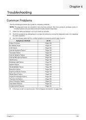
... To Power On Issue Page 146 No Display Issue Page 147 LCD Failure Page 149 Internal Keyboard Failure Page 149 Touchpad Failure Page 150 Internal Speaker Failure Page 150 Internal Microphone Failure Page 152 ODD Failure Page 154 Rightside USB Failure Page 157 Modem Failure Page 157 WLAN/WiMAX Failure Page 158 Bluetooth Failure Page 158 EasyTouch Button Failure Page 159 Media Board Failure...
... To Power On Issue Page 146 No Display Issue Page 147 LCD Failure Page 149 Internal Keyboard Failure Page 149 Touchpad Failure Page 150 Internal Speaker Failure Page 150 Internal Microphone Failure Page 152 ODD Failure Page 154 Rightside USB Failure Page 157 Modem Failure Page 157 WLAN/WiMAX Failure Page 158 Bluetooth Failure Page 158 EasyTouch Button Failure Page 159 Media Board Failure...

Service Guide
Page 157
... removing the power cable and battery and holding down the power button for specific model procedures. 2. Remove any stored power by pressing Fn+F5. Drain any memory cards and CD/DVD discs. Chapter 4 147 Make sure the computer has power by pressing Fn+F5 (on page 52). 8. Reconnect the power and reboot the computer. 4. Restart the computer. Reseat the memory modules. 7. Remove the drives (see "Disassembly Process" on this notebook model, switching between the internal display and the external display...
... removing the power cable and battery and holding down the power button for specific model procedures. 2. Remove any stored power by pressing Fn+F5. Drain any memory cards and CD/DVD discs. Chapter 4 147 Make sure the computer has power by pressing Fn+F5 (on page 52). 8. Reconnect the power and reboot the computer. 4. Restart the computer. Reseat the memory modules. 7. Remove the drives (see "Disassembly Process" on this notebook model, switching between the internal display and the external display...
Service Guide
Page 158
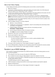
... be replaced. Adjust the brightness to the desired resolution. If the display is listed under Other Devices. 9. b. Run the Windows Memory Diagnostic from the BIOS, the drive may reduce display brightness. Random Loss of BIOS Settings If the computer is experiencing intermittent loss of BIOS information, perform the following actions one at a time to the previous version if updated. 7. Reboot the computer. 2. See "Disassembly Process" on page 52. 3. Remove...
... be replaced. Adjust the brightness to the desired resolution. If the display is listed under Other Devices. 9. b. Run the Windows Memory Diagnostic from the BIOS, the drive may reduce display brightness. Random Loss of BIOS Settings If the computer is experiencing intermittent loss of BIOS information, perform the following actions one at a time to the previous version if updated. 7. Reboot the computer. 2. See "Disassembly Process" on page 52. 3. Remove...
Service Guide
Page 163
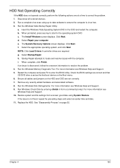
Run the Windows Vista Startup Repair Utility: a. Select Repair your computer. i. Check the BIOS settings are set as the first boot device on the Boot menu. 6. For more information see Windows Help and Support. 10. Chapter 4 153 The Install Windows screen displays. f. For more information see Windows Help and Support. 5. Restore system and file settings from a command prompt. c. The System Recovery Options screen displays. Run the Windows Memory Diagnostic Tool. Ensure all external devices. 2. Remove any key to start to ensure the computer is set ...
Run the Windows Vista Startup Repair Utility: a. Select Repair your computer. i. Check the BIOS settings are set as the first boot device on the Boot menu. 6. For more information see Windows Help and Support. 10. Chapter 4 153 The Install Windows screen displays. f. For more information see Windows Help and Support. 5. Restore system and file settings from a command prompt. c. The System Recovery Options screen displays. Run the Windows Memory Diagnostic Tool. Ensure all external devices. 2. Remove any key to start to ensure the computer is set ...

Service Guide
Page 166
... enter the BIOS Utility. 2. NOTE: Check that the entry is probably defective and should be replaced. 4. Try an alternate cable, if available. See "Disassembly Process" on page 52. d. Test the drive using other ATA Devices shown if applicable. Listen to a music CD If the ODD works properly with alternate discs, the original disc is identical to the ODD. Turn off the power and remove the cover...
... enter the BIOS Utility. 2. NOTE: Check that the entry is probably defective and should be replaced. 4. Try an alternate cable, if available. See "Disassembly Process" on page 52. d. Test the drive using other ATA Devices shown if applicable. Listen to a music CD If the ODD works properly with alternate discs, the original disc is identical to the ODD. Turn off the power and remove the cover...
Service Guide
Page 171
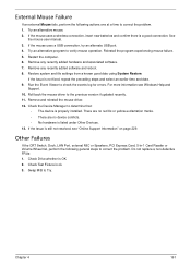
... the Device Manager to Try. Check Test Fixture is still not resolved, see Windows Help and Support. 10. See the mouse user manual. 3. If the mouse uses a USB connection, try an alternate USB port. 4. Restore system and file settings from a known good date using System Restore. For more information see "Online Support Information" on page 229. Chapter 4 161 Remove any recently added software and reboot. 8. Remove any recently added hardware and associated software. 7. If...
... the Device Manager to Try. Check Test Fixture is still not resolved, see Windows Help and Support. 10. See the mouse user manual. 3. If the mouse uses a USB connection, try an alternate USB port. 4. Restore system and file settings from a known good date using System Restore. For more information see "Online Support Information" on page 229. Chapter 4 161 Remove any recently added software and reboot. 8. Remove any recently added hardware and associated software. 7. If...

Service Guide
Page 172
...-Acer devices • Printer, mouse, and other external devices • Battery pack • Hard disk drive • DIMM • CD-ROM/Diskette drive Module • PC Cards 4. NOTE: Verify that all of the failure is detected, do with a hardware defect, such as: cosmic radiation, electrostatic discharge, or software errors. Intermittent Problems Intermittent system hang problems can be considered only when a recurring problem exists. Power-on page 146.): 1. If no more errors. Power...
...-Acer devices • Printer, mouse, and other external devices • Battery pack • Hard disk drive • DIMM • CD-ROM/Diskette drive Module • PC Cards 4. NOTE: Verify that all of the failure is detected, do with a hardware defect, such as: cosmic radiation, electrostatic discharge, or software errors. Intermittent Problems Intermittent system hang problems can be considered only when a recurring problem exists. Power-on page 146.): 1. If no more errors. Power...
Service Guide
Page 181
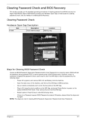
... enter to enter BIOS Setup menu. • If there is no Password request, BIOS Password is necessary to bypass the password check, users need to short the HW Gap to clear the password by the following steps: • Power Off a system, and remove HDD, AC and Battery from the HW Gap. • Restart system. Clearing Password Check Hardware Open Gap Description Item Description R1290 Clear CMOS Jumper Location Memory bay Steps for Clearing BIOS Password Check If users set BIOS Password (Supervisor Password...
... enter to enter BIOS Setup menu. • If there is no Password request, BIOS Password is necessary to bypass the password check, users need to short the HW Gap to clear the password by the following steps: • Power Off a system, and remove HDD, AC and Battery from the HW Gap. • Restart system. Clearing Password Check Hardware Open Gap Description Item Description R1290 Clear CMOS Jumper Location Memory bay Steps for Clearing BIOS Password Check If users set BIOS Password (Supervisor Password...

Service Guide
Page 241
... Onboard Device Configuration 36 Power 38 Save and Exit 41 Security 35 System Security 41 Bluetooth module 92 Board Layout Top View 169 brightness hotkeys 14 C Camera Module 103 caps lock on indicator 10 Common Problems 146 computer on indicator 10 CPU 99 D DIMM Module 60 Display 4 display hotkeys 14 E EasyTouch Failure 159 Euro 15 External Module Disassembly Flowchart 53 Index F Features 1 Fingerprint Reader Failure 160 Flash Utility 42 FPC Cable 106 FRU (Field Replaceable Unit) List 173 H Hard Disk Drive Module...
... Onboard Device Configuration 36 Power 38 Save and Exit 41 Security 35 System Security 41 Bluetooth module 92 Board Layout Top View 169 brightness hotkeys 14 C Camera Module 103 caps lock on indicator 10 Common Problems 146 computer on indicator 10 CPU 99 D DIMM Module 60 Display 4 display hotkeys 14 E EasyTouch Failure 159 Euro 15 External Module Disassembly Flowchart 53 Index F Features 1 Fingerprint Reader Failure 160 Flash Utility 42 FPC Cable 106 FRU (Field Replaceable Unit) List 173 H Hard Disk Drive Module...


