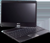
Acer Aspire 1820PT, Aspire 1820PTZ, Aspire 1420P Quick Guide
Page 5
.... 6 Power1 Indicates the computer's power status. Fully charged: The light shows blue when in AC mode. Battery1 Bluetooth communication indicator Communication indicator Indicates the computer's battery status. 1. Caps Lock Lights up . The front panel indicators are visible even when the computer cover is activated. Num Lock Lights up when Num Lock...
Acer Aspire 1820PT, Aspire 1820PTZ, Aspire 1420P Quick Guide
Page 7
7 Closed front view English 1 2 # Icon 1 2 Item Communication key Speakers Description Enables / disables the WLAN / 3G functions. Rear view # Icon 1 Item Battery bay 1 Description Houses the computer's battery pack. Left and right speakers deliver stereo audio output.
Acer Aspire 1820PT, Aspire 1820PTZ, Aspire 1420P Quick Guide
Page 10
English 10 Base view 1 6 2 5 4 3 # Icon Item 1 Battery bay Description Houses the computer's battery pack. 2 Hard disk bay Houses the computer's hard disk (secured with screws). 3 Memory compartment Houses the computer's main memory. 4 Ventilation slots and Enable the computer to stay cool, even cooling fan after prolonged use. Note: Do not cover or obstruct the opening of the fan. 5 Battery lock Locks the battery in position. 6 Battery release latch Releases the battery for removal.
Aspire 1420P and 1820PT Service Guide
Page 7
... 39 Pre-disassembly Instructions 39 Disassembly Process 40 External Module Disassembly Process 41 External Modules Disassembly Flowchart 41 Removing the Dummy Card 42 Removing the Battery Pack 42 Removing the SIM Card 43 Removing the Module Cover 44 Removing the Hard Disk Drive Module 45 Removing the DIMM Module 47 Removing...
Aspire 1420P and 1820PT Service Guide
Page 8
... 67 Removing the LED Board 68 Removing the CRT Board 71 Removing the Mainboard 73 Removing the Thermal Module 76 Removing the RTC Battery 77 Removing the Speaker Modules 77 Removing the LCD Module 78 LCD Module Disassembly Process 80 LCD Module Disassembly Flowchart 80 Removing the ...105 Replacing the Camera Board 106 Replacing the LCD Bezel 107 Main Unit Reassembly Process 110 Replacing the LCD Module 110 Replacing the RTC Battery 112 Replacing the Thermal Module 112 Replacing the Speakers 113 Replacing the Mainboard 115 Replacing the CRT Board 117 Replacing the LED Board ...
Aspire 1420P and 1820PT Service Guide
Page 15
... charging. 2. Fully charged: The light shows blue when in AC mode. Chapter 1 5 Battery Bluetooth communication indicator Communication indicator Indicates the computer's battery status. 1. No. 1 2 1 2 Icon Item Communication key Description Enables / disables the WLAN / 3G functions. Indicates the status of Bluetooth communication. (only for certain models) Indicates the ...
Aspire 1420P and 1820PT Service Guide
Page 17
... keyless models are also available. Houses the computer's hard disk (secured with screws). Houses the computer's main memory. Releases the battery for removal. Connects to secure the lock. Chapter 1 7 Locks the battery in position. Note: Wrap the computer security lock cable around an immovable object such as a table or handle of the... fan. Insert the lock into the notch and turn the key to an Ethernet 10/100/1000-based network. 1 6 2 5 4 3 No. 1 2 3 4 5 6 Icon Item Battery bay Hard disk bay Memory compartment Ventilation slots and cooling fan...
Aspire 1420P and 1820PT Service Guide
Page 18
... is activated. Fully charged: The light shows green when in AC mode. 8 Chapter 1 HDD Num Lock Caps Lock Battery Indicates when the hard disk drive is charging. 2. Lights up when Caps Lock is closed. Indicates the computer...'s battery status. Charging: The battery light shows amber when the battery is active. Rear View No. 1 Icon Item Battery bay 1 Description Houses the computer's battery pack. The battery indicator is visible even when the computer cover is activated. NOTE: 1....
Aspire 1420P and 1820PT Service Guide
Page 31
... RISC core, with up to 4 Mbytes of external address space, running at up to 25 MHz. • 128-pin LQChipFP Battery Item Vendor & model name Battery Type Pack capacity Number of battery cell Package configuration Normal voltage Charge voltage Specifications 6 Cell SIMPLO UM09F70 3S2P SANYO UM09F36 3S2P Li-ion SANYO 6 cell 5600mAh SAMSUNG...
Aspire 1420P and 1820PT Service Guide
Page 50
... Part Number M2*2.5 (silver) 8 86.TPK07.001 M2*3 7 86.ARE07.002 M2*4 26 86.W0107.003 M2*5 24 86.TG607.004 40 Chapter 3 Remove the battery pack.
Aspire 1420P and 1820PT Service Guide
Page 51
External Module Disassembly Process NOTE: The product previews seen in the disassembly procedures may not represent the final product color or configuration. External Modules Disassembly Flowchart Turn off system and peripherals power Disconnect power and signal cables from system Remove Dummy Card Remove Battery Remove SIM Card (Optional) Remove Lower Cover Remove HDD Remove DIMM Remove WLAN Board Remove 3G Board Screw List Step WLAN 3G Module Screw M2*3 M2*3 Quantity 1 1 Part No. 86.ARE07.002 86.ARE07.002 Chapter 3 41
Aspire 1420P and 1820PT Service Guide
Page 52
Removing the Battery Pack 1. Removing the Dummy Card 1. Turn the computer over. 2. Pull the dummy card out. Slide the battery lock/unlock latch to spring out. 2. Press the card in to allow it to the unlock position. 42 Chapter 3
Aspire 1420P and 1820PT Service Guide
Page 53
See "Removing the Dummy Card" on page 42. 2. Slide and hold the battery release latch to the release position (1), grasp the battery edge closest to spring out. 3. 3. Press the SIM card in to allow it to the release latch and pull the battery up and away (2). 2 1 Removing the SIM Card 1. Remove the SIM card. Chapter 3 43
Aspire 1420P and 1820PT Service Guide
Page 61
... Covers Remove Upper Cover Remove Button Board Remove LED Board Remove CRT Board Remove I/O Board Remove Bluetooth Module Remove Thermal Module Remove Mainboard Remove RTC Battery Remove Speaker Module Remove LCD Module Chapter 3 51 NOTE: The product previews seen in the same position. During the removal and replacement of components, ensure...
Aspire 1420P and 1820PT Service Guide
Page 87
Remove the two (2) screws. See "Removing the Mainboard" on page 73. 2. Chapter 3 77 Removing the Speaker Modules 1. See "Removing the Mainboard" on page 73. 2. Step Speaker Screw M2*3 Quantity 2 Screw Type. Removing the RTC Battery 1. Carefully lift the battery out of the main board.
Aspire 1420P and 1820PT Service Guide
Page 122
Place the thermal module on the main board. 112 Chapter 3 Remove all heat pads are approved for use: • Eapus XR-PE 1. Replacing the Thermal Module IMPORTANT: Ensure all traces of thermal grease or pad adhesive from the CPU and thermal module using a lint-free cloth or cotton swab and Isopropyl Alcohol, Acetone, or other approved cleaning agent. 2. The following thermal pads are in place before replacing the Thermal Module. Replacing the RTC Battery 1. Push the RTC battery into the holder.
Aspire 1420P and 1820PT Service Guide
Page 151
Push the battery down into the slots. 2. Replacing the Battery 1. Insert the battery outer edge into place. Replacing the SIM Card 1. Chapter 3 141 Insert the SIM card into the slot.
Aspire 1420P and 1820PT Service Guide
Page 152
Insert the dummy card into the slot. 142 Chapter 3 Replacing the Dummy Card 1. 3. Lock the battery.
Aspire 1420P and 1820PT Service Guide
Page 154
... computer and the electrical outlet. Remove any recently installed software. 6. Do not replace non-defective FRUs: SSttaarrtt OK Check AC/Battery Power on OK Check Daughter/B & FFC Whether OK Swap AC /Battery NG to try OK Swap Daughter/B NG Re-plug PWR FFC Swap M/B Computer Shuts down Intermittently If the system powers...
Aspire 1420P and 1820PT Service Guide
Page 155
... the main board CPU Thermal Remove and Module properly No replace thermal connected? Make sure the computer has power by removing the power cable and battery and holding down the power button for specific model procedures. 2. No Display Issue If the Display doesn't work, perform the following actions one at a time...