
AL1912 Service Guide
Page 7
... CONTROLS ...30 MAIN OSD MENU...31 OSD MESSAGE...33 PLUG AND PLAY ...35 WHITE COLOR TEMPERATURE...36 AUDIO TECHNICAL SPECIFICATION (FOR AL1912 m ONLY 36 SPEAKERS ...37 Chapter 3 Machine Disassembly and Replacement 38 DISASSEMBLY PROCEDURE ...38 Chapter 4 Troubleshooting 41 TROUBLESHOOTING ...41 Chapter 5 Connector Information 45 CONNECTOR INFORMATION ...45 Chapter 6 FRU List 46 FRU (Field...
... CONTROLS ...30 MAIN OSD MENU...31 OSD MESSAGE...33 PLUG AND PLAY ...35 WHITE COLOR TEMPERATURE...36 AUDIO TECHNICAL SPECIFICATION (FOR AL1912 m ONLY 36 SPEAKERS ...37 Chapter 3 Machine Disassembly and Replacement 38 DISASSEMBLY PROCEDURE ...38 Chapter 4 Troubleshooting 41 TROUBLESHOOTING ...41 Chapter 5 Connector Information 45 CONNECTOR INFORMATION ...45 Chapter 6 FRU List 46 FRU (Field...

AL1912 Service Guide
Page 38
Remove the neck cover. 2. To separate the chassis and bezel. 7. Remove the four screws to release the back cover. 2. Then take the chassis. 5. Remove the two screws to release the EMI cover from bezel. 6. Remove the four screws to release the hinge. 3. Remove the two screws from chassis. 3. Remove the two screws from chassis and release the panel. 38 Remove the four screws from VGA connector. 4. Chapter 3 Machine Disassembly and Replacement Disassembly Procedure Disassemble the base 1. Remove the base Disassemble the chassis 1.
Remove the neck cover. 2. To separate the chassis and bezel. 7. Remove the four screws to release the back cover. 2. Then take the chassis. 5. Remove the two screws to release the EMI cover from bezel. 6. Remove the four screws to release the hinge. 3. Remove the two screws from chassis. 3. Remove the two screws from chassis and release the panel. 38 Remove the four screws from VGA connector. 4. Chapter 3 Machine Disassembly and Replacement Disassembly Procedure Disassemble the base 1. Remove the base Disassemble the chassis 1.
AL1912 Service Guide
Page 39
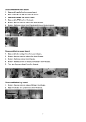
.... Remove the three screws from VL board. 5. Remove the three screws from VL board. 3. Disassemble the key board 1. Disassemble two VL-VK lines from Chassis. 4. Disassemble two voltage lines from the chassia. Remove the one screw to release line from Chassis. 3. Then... two screws to release VK board from Chassis. 6. Disassemble power line from power board. 2. Remove the one screw to release line from bezel. 2. Disassemble the two speaker lines from Chassis. 5. Disassemble the main board 1. Disassemble the power board 1. Remove the one screw to release...
.... Remove the three screws from VL board. 5. Remove the three screws from VL board. 3. Disassemble the key board 1. Disassemble two VL-VK lines from Chassis. 4. Disassemble two voltage lines from the chassia. Remove the one screw to release line from Chassis. 3. Then... two screws to release VK board from Chassis. 6. Disassemble power line from power board. 2. Remove the one screw to release line from bezel. 2. Disassemble the two speaker lines from Chassis. 5. Disassemble the main board 1. Disassemble the power board 1. Remove the one screw to release...
AL1912 Service Guide
Page 40
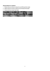
Remove the four screws from bezel. 3. Remove the two screws to release line and VK board from bezel. 2. Disassemble the speakers 1. Remove the two screws to release line and chassis from bezel. 40
Remove the four screws from bezel. 3. Remove the two screws to release line and VK board from bezel. 2. Disassemble the speakers 1. Remove the two screws to release line and chassis from bezel. 40


