
AL1706 Service Guide
Page 5
... (FOR FCC CERTIFIED MODELS) NOTE: This equipment has been tested and found to comply with the limits for a Class B digital device, pursuant to which can radiate radio frequency energy, and if not installed and used in a residential installation. Connect the equipment into an outlet on , the user is encouraged to try to comply with the instructions, may cause harmful...
... (FOR FCC CERTIFIED MODELS) NOTE: This equipment has been tested and found to comply with the limits for a Class B digital device, pursuant to which can radiate radio frequency energy, and if not installed and used in a residential installation. Connect the equipment into an outlet on , the user is encouraged to try to comply with the instructions, may cause harmful...
AL1706 Service Guide
Page 7
... plug will protect the monitor from damage due to qualified service personnel. SPECIAL NOTES ON LCD MONITORS The following the kit instructions. Never push any object into a grounded power outlet as a missing pixel or a pixel lit all servicing to power surges. Never spill liquids on the monitor cabinet. Turn off the Power Switch and then turn it will not be used for ventilation. User only a trolley or stand recommended...
... plug will protect the monitor from damage due to qualified service personnel. SPECIAL NOTES ON LCD MONITORS The following the kit instructions. Never push any object into a grounded power outlet as a missing pixel or a pixel lit all servicing to power surges. Never spill liquids on the monitor cabinet. Turn off the Power Switch and then turn it will not be used for ventilation. User only a trolley or stand recommended...
AL1706 Service Guide
Page 9
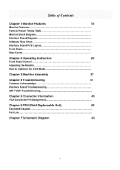
... 10 Monitor Features Factory Preset Timing Table Monitor Block Diagram Interface Board Diagram Software Flow Chart Interface Board PCB Layout Front Bezel Rear Cover Chapter 2 Operating Instruction 20 Front Bezel Control Adjusting the Monitor How to Optimize the DOS-Mode Chapter 3 Machine Assembly 27 Chapter 4 Troubleshooting 31 Common Acknowledge Interface Board Troubleshooting QPI PCBA Troubleshooting Chapter 5 Connector Information 40 VGA Connector Pin Assignment Chapter 6 FRU (Field Replaceable Unit) 42 Exploded Diagram Part List...
... 10 Monitor Features Factory Preset Timing Table Monitor Block Diagram Interface Board Diagram Software Flow Chart Interface Board PCB Layout Front Bezel Rear Cover Chapter 2 Operating Instruction 20 Front Bezel Control Adjusting the Monitor How to Optimize the DOS-Mode Chapter 3 Machine Assembly 27 Chapter 4 Troubleshooting 31 Common Acknowledge Interface Board Troubleshooting QPI PCBA Troubleshooting Chapter 5 Connector Information 40 VGA Connector Pin Assignment Chapter 6 FRU (Field Replaceable Unit) 42 Exploded Diagram Part List...
AL1706 Service Guide
Page 10
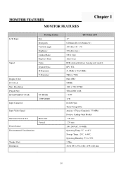
MONITOR FEATURES LCD Panel Signal Display Color Dot Clock Max. H-Frequency V-Frequency ON MODE OFF MODE Input Video Signal Maximum Screen Size Power Source Environmental Considerations Horizontal Vertical Weight (Net) Dimension TFT Color LCD 17" 0.264mm (H) x 0.264mm (V) 140゚(H), 140 ゚(V) 270cd/m2 (typ.) 500:1 (typ.) 12ms (typ.) RGB Analog Interface (Analog only model) H/V TTL 31.5KHz to 60.241KHz 56Hz to 75Hz 6bits+FRC 80MHz 1024 x 768 @75Hz VESA DDC 1/2B < 35W Resolution Plug & Play EPA ENGERGY STAR Input Connector Driving...
MONITOR FEATURES LCD Panel Signal Display Color Dot Clock Max. H-Frequency V-Frequency ON MODE OFF MODE Input Video Signal Maximum Screen Size Power Source Environmental Considerations Horizontal Vertical Weight (Net) Dimension TFT Color LCD 17" 0.264mm (H) x 0.264mm (V) 140゚(H), 140 ゚(V) 270cd/m2 (typ.) 500:1 (typ.) 12ms (typ.) RGB Analog Interface (Analog only model) H/V TTL 31.5KHz to 60.241KHz 56Hz to 75Hz 6bits+FRC 80MHz 1024 x 768 @75Hz VESA DDC 1/2B < 35W Resolution Plug & Play EPA ENGERGY STAR Input Connector Driving...
AL1706 Service Guide
Page 12
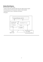
Power/inverter board: Provide power to control the LCD monitor. 4. Flat panel: Flat panel (LVDS interface) and CCFL Inverter/Power BD (Including AC/DC Power Supply and Inverter) Interface Board (VGA input) Keypad BD AC input Range 90V~264V Host computer (VGA signal input and DDC) 12 Monitor Block Diagram The LCD monitor contains 4 parts: 1. Keypad board: For user to interface board and panel 3. interface board: Deal with VGA input signal and output the signal to panel. 2.
Power/inverter board: Provide power to control the LCD monitor. 4. Flat panel: Flat panel (LVDS interface) and CCFL Inverter/Power BD (Including AC/DC Power Supply and Inverter) Interface Board (VGA input) Keypad BD AC input Range 90V~264V Host computer (VGA signal input and DDC) 12 Monitor Block Diagram The LCD monitor contains 4 parts: 1. Keypad board: For user to interface board and panel 3. interface board: Deal with VGA input signal and output the signal to panel. 2.
AL1706 Service Guide
Page 14
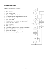
... user value and mode setting from EEProm. 5. Check the analog port, are there any key pressed? (1) (2) Y (3) No (4) (5) Y (6) No (7) No (8) Y (10) (9) (11) (12) (13) (14) Y No 14 Enter sleep mode. 10. Display "No Signal" message. 9. Wake up the scalar. 11. Is the EEProm blank? 3. Process the OSD display 14. Software Flow Chart ACER 17" flow chart item description: 1. Program the scalar to be able to green color...
... user value and mode setting from EEProm. 5. Check the analog port, are there any key pressed? (1) (2) Y (3) No (4) (5) Y (6) No (7) No (8) Y (10) (9) (11) (12) (13) (14) Y No 14 Enter sleep mode. 10. Display "No Signal" message. 9. Wake up the scalar. 11. Is the EEProm blank? 3. Process the OSD display 14. Software Flow Chart ACER 17" flow chart item description: 1. Program the scalar to be able to green color...
AL1706 Service Guide
Page 19
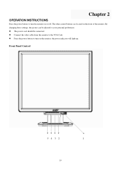
Chapter 2 OPERATION INSTRUCTIONS Press the power button to your personal preferences. By changing these settings, the picture can be connected. Connect the video cable from the monitor to turn the monitor on or off. The power cord should be adjusted to turn on the front of the monitor. Press the power button to the VGA Card. Front Panel Control 5 4 3 2 1 19 The other control buttons are located on the monitor, the power indicator will light up.
Chapter 2 OPERATION INSTRUCTIONS Press the power button to your personal preferences. By changing these settings, the picture can be connected. Connect the video cable from the monitor to turn the monitor on or off. The power cord should be adjusted to turn on the front of the monitor. Press the power button to the VGA Card. Front Panel Control 5 4 3 2 1 19 The other control buttons are located on the monitor, the power indicator will light up.
AL1706 Service Guide
Page 20
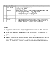
... the volume control when the OSD is ON or Exit OSD menu when in a place subject to direct sunlight, or excessive dust or mechanical vibration or shock. No Symbol 1 Power key/LED 2 Menu/Enter 3 > 4 < 5 Auto/Exit Function Press this button to turn the monitor on or off or activate/de-activate adjustment function when OSD is OFF. 2. Power On mode LED Orange - Off mode Activate OSD menu when OSD is off LED Green - Adjust...
... the volume control when the OSD is ON or Exit OSD menu when in a place subject to direct sunlight, or excessive dust or mechanical vibration or shock. No Symbol 1 Power key/LED 2 Menu/Enter 3 > 4 < 5 Auto/Exit Function Press this button to turn the monitor on or off or activate/de-activate adjustment function when OSD is OFF. 2. Power On mode LED Orange - Off mode Activate OSD menu when OSD is off LED Green - Adjust...
AL1706 Service Guide
Page 22
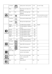
... Set OSD language to French N/A N/A Set OSD language to Spain N/A N/A Set OSD language to Italian N/A N/A Set OSD Language to Simplified N/A Chinese N/A Set OSD language to Japanese N/A Adjust OSD horizontal position 0-100 50 V. V. from EEPROM Red gain from digital register N/A N/A 0-100 Green gain from digital register 0-100 N/A N/A The value which we get after executing Auto color balance User/Blue Blue gain from EEPROM Recall cool color temp. Position Adjust picture vertical position 0-100 Do Auto Config Warm N/A Cool N/A User/Red User/Green Recall warm color...
... Set OSD language to French N/A N/A Set OSD language to Spain N/A N/A Set OSD language to Italian N/A N/A Set OSD Language to Simplified N/A Chinese N/A Set OSD language to Japanese N/A Adjust OSD horizontal position 0-100 50 V. V. from EEPROM Red gain from digital register N/A N/A 0-100 Green gain from digital register 0-100 N/A N/A The value which we get after executing Auto color balance User/Blue Blue gain from EEPROM Recall cool color temp. Position Adjust picture vertical position 0-100 Do Auto Config Warm N/A Cool N/A User/Red User/Green Recall warm color...
AL1706 Service Guide
Page 25
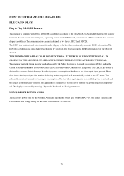
...). This reduces the monitor's internal power supply consumption. After the video input signal is restored, full power is restored and the display is defined in two levels, DDC1 and DDC2B. The voltage rating for the Northern American region is the wallet plug with VESA DDC1/2B capabilities according...monitor meets the Green monitor standards as set by pressing a key on the I2C protocol. The communication channel is automatically redrawn. The DDC2B is UL listed and CSA labeled. USING RIGHT POWER CORD The accessory power cord for the power cord shall be 125 volts AC. 25 The display...
...). This reduces the monitor's internal power supply consumption. After the video input signal is restored, full power is restored and the display is defined in two levels, DDC1 and DDC2B. The voltage rating for the Northern American region is the wallet plug with VESA DDC1/2B capabilities according...monitor meets the Green monitor standards as set by pressing a key on the I2C protocol. The communication channel is automatically redrawn. The DDC2B is UL listed and CSA labeled. USING RIGHT POWER CORD The accessory power cord for the power cord shall be 125 volts AC. 25 The display...
AL1706 Service Guide
Page 26
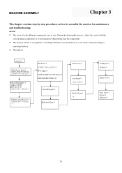
... assemble the monitor for the different components vary in size. Wear gloves Chassis*1 PCBA Power Board *1 INSULATOR PC,MYLAR SCREW (PW 3*6,M,ZN) *3 PCBA I/F BOARD *1 CABLE 30P FFC HRN ASS'Y 8P SCREW (PW 3*6,M,ZN) *3 INL Panel*1 SCREW (PW3x4,M,ZN)*4 FFC(30pin)*1 TAPE,ACE#LP1701(40x20mm)*1 INSULATOR PC#LE1710 Insert B/L jack*4 PCBA Control Board *1 SCREW (PW 3*4,M,ZN) *2 EMI shield Tape*2 Back cover*1 Arm Stand*1 (M4x10,ZN)*4 Bracket Finger *1 Stand...
... assemble the monitor for the different components vary in size. Wear gloves Chassis*1 PCBA Power Board *1 INSULATOR PC,MYLAR SCREW (PW 3*6,M,ZN) *3 PCBA I/F BOARD *1 CABLE 30P FFC HRN ASS'Y 8P SCREW (PW 3*6,M,ZN) *3 INL Panel*1 SCREW (PW3x4,M,ZN)*4 FFC(30pin)*1 TAPE,ACE#LP1701(40x20mm)*1 INSULATOR PC#LE1710 Insert B/L jack*4 PCBA Control Board *1 SCREW (PW 3*4,M,ZN) *2 EMI shield Tape*2 Back cover*1 Arm Stand*1 (M4x10,ZN)*4 Bracket Finger *1 Stand...
AL1706 Service Guide
Page 30
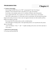
... the analog circuit part, if only some scale appears abnormal color that stand the problem happen in the digital circuit part. If you change the M/B, Please re-do "DDC" programmed &"Auto Color balance" If Replace "Power & Inverter board" only, please re-do it under 16-grey scalar pattern. TROUBLESHOOTING Chapter 4 1. So if the entire screen is out of Windows shut down pattern. If you check the H/V position, please use...
... the analog circuit part, if only some scale appears abnormal color that stand the problem happen in the digital circuit part. If you change the M/B, Please re-do "DDC" programmed &"Auto Color balance" If Replace "Power & Inverter board" only, please re-do it under 16-grey scalar pattern. TROUBLESHOOTING Chapter 4 1. So if the entire screen is out of Windows shut down pattern. If you check the H/V position, please use...
AL1706 User's Guide
Page 1
Table of Contents Precautions ...2 Special notes on LCD monitors 3 Package contents ...3 Installation instructions 4 Assembling the Monitor...4 Detaching the Monitor ...4 Adjusting the Viewing Angle...4 Connecting the Devices...5 Switching the Power ...5 Adjusting display settings 6 External Controls ...6 OSD options ...7 OSD Menu ...7 Troubleshooting ...9 General specifications 10 1
Table of Contents Precautions ...2 Special notes on LCD monitors 3 Package contents ...3 Installation instructions 4 Assembling the Monitor...4 Detaching the Monitor ...4 Adjusting the Viewing Angle...4 Connecting the Devices...5 Switching the Power ...5 Adjusting display settings 6 External Controls ...6 OSD options ...7 OSD Menu ...7 Troubleshooting ...9 General specifications 10 1
AL1706 User's Guide
Page 2
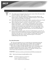
...monitor it is best to lightly spray on the back or top of heat. care very much about our environment protection strategy and firmly believe that it from the display screen, including sprays. The monitor should be used to repair the monitor by yourself; When cleaning this monitor, disconnect it helps... problem, please check the "Troubleshooting" section first. Do not allow sharp objects such as the monitor requires ventilation. On the contrary, other hazards. If such objects touch the screen, the LCD panel will clean stubborn stains. opening or removing covers ...
...monitor it is best to lightly spray on the back or top of heat. care very much about our environment protection strategy and firmly believe that it from the display screen, including sprays. The monitor should be used to repair the monitor by yourself; When cleaning this monitor, disconnect it helps... problem, please check the "Troubleshooting" section first. Do not allow sharp objects such as the monitor requires ventilation. On the contrary, other hazards. If such objects touch the screen, the LCD panel will clean stubborn stains. opening or removing covers ...
AL1706 User's Guide
Page 3
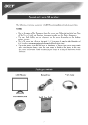
... brightness on the screen depending on the desktop pattern you use . LCD Monitor Package contents Power Cord VGA Cable User Manual (CD) Quick Start Guide 3 Turn off the Power Switch for hours. Special notes on again to the nature of the LCD screen, an afterimage of the previous screen may flicker during initial use . • The LCD screen has effective pixels of 99.99% or more. NOTES • Due to the nature of the fluorescent light...
... brightness on the screen depending on the desktop pattern you use . LCD Monitor Package contents Power Cord VGA Cable User Manual (CD) Quick Start Guide 3 Turn off the Power Switch for hours. Special notes on again to the nature of the LCD screen, an afterimage of the previous screen may flicker during initial use . • The LCD screen has effective pixels of 99.99% or more. NOTES • Due to the nature of the fluorescent light...
AL1706 User's Guide
Page 4
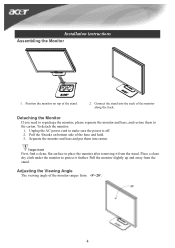
... the base and hold. 3. Detaching the Monitor If you need to place the monitor after removing it further. Pull the 4 hooks on top of the monitor ranges from -5°~20°. 4 Unplug the AC power cord to protect it from the stand. Place a clean dry cloth under the monitor to make sure the power is off. 2. Adjusting the Viewing Angle The viewing angle of the stand. 2. Installation instructions Assembling the Monitor 1. Connect the stand into...
... the base and hold. 3. Detaching the Monitor If you need to place the monitor after removing it further. Pull the 4 hooks on top of the monitor ranges from -5°~20°. 4 Unplug the AC power cord to protect it from the stand. Place a clean dry cloth under the monitor to make sure the power is off. 2. Adjusting the Viewing Angle The viewing angle of the stand. 2. Installation instructions Assembling the Monitor 1. Connect the stand into...
AL1706 User's Guide
Page 5
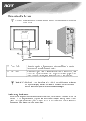
... plug of the graphics card on the computer. Switching the Power First, switch the power on to the monitor, then switch the power on the power button or a video signal, check the connections. 5 Connect the signal cable to the VGA input socket of the monitor , and connect the signal cable to the power cord which should then be inserted into , and that the computer and the monitor are bent or otherwise damaged. Allow about 10 seconds for use. Power Code VGA Cable...
... plug of the graphics card on the computer. Switching the Power First, switch the power on to the monitor, then switch the power on the power button or a video signal, check the connections. 5 Connect the signal cable to the VGA input socket of the monitor , and connect the signal cable to the power cord which should then be inserted into , and that the computer and the monitor are bent or otherwise damaged. Allow about 10 seconds for use. Power Code VGA Cable...
AL1706 User's Guide
Page 7
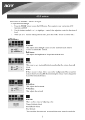
... size. Press the MENU button to the desired level. 3. COLOR: There are any horizontal distortion and makes the picture clear and sharp. OSD Menu Contrast: This adjusts dark and light shades of the picture on the background of adjusting color: Warm (Reddish white) Cool (Bluish white) User defined: You can adjust the colors red, green and blue to the intensity you have finished making all selections, press the AUTO button to exit the OSD. Brightness: This adjusts the brightness of color...
... size. Press the MENU button to the desired level. 3. COLOR: There are any horizontal distortion and makes the picture clear and sharp. OSD Menu Contrast: This adjusts dark and light shades of the picture on the background of adjusting color: Warm (Reddish white) Cool (Bluish white) User defined: You can adjust the colors red, green and blue to the intensity you have finished making all selections, press the AUTO button to exit the OSD. Brightness: This adjusts the brightness of color...
AL1706 User's Guide
Page 9
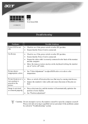
Troubleshooting Problems Power LED is not ON No Picture Possible Solutions • Check to see if the power switch is in the ON position. • Ensure that the Power Cord is connected. • Check to see if the power switch is in the picture • Inspect the monitor's video cable and ensure that may be solved in "Troubleshooting" section. 9 Picture shows • See "Color Adjustment" to adjust RGB color or to service the monitor yourself or open the computer yourself...
Troubleshooting Problems Power LED is not ON No Picture Possible Solutions • Check to see if the power switch is in the ON position. • Ensure that the Power Cord is connected. • Check to see if the power switch is in the picture • Inspect the monitor's video cable and ensure that may be solved in "Troubleshooting" section. 9 Picture shows • See "Color Adjustment" to adjust RGB color or to service the monitor yourself or open the computer yourself...
AL1706 User's Guide
Page 10
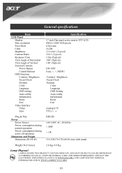
... Item LCD Panel Display Max resolution Pixel Pitch Color Brightness Contrast Ratio Response Time View Angle of Horizontal View Angle of Vertical External Controls Power Button Control Buttons OSD Function Contrast /Brightness Focus/Clock Position Color Language OSD setting Auto config Information Reset Exit Video Interface Video Sync Specification 17-inch Flat panel active-matrix TFT LCD SXGA 1280×1024 pixels 0.264 mm 16.2M 270 cd/m² (Typical) 500:1 (Typical) 12ms (Typical) 140° (Typical) 140° (Typical) ON/ OFF Auto, , MENU Contrast / Brightness Focus/Clock Position Color...
... Item LCD Panel Display Max resolution Pixel Pitch Color Brightness Contrast Ratio Response Time View Angle of Horizontal View Angle of Vertical External Controls Power Button Control Buttons OSD Function Contrast /Brightness Focus/Clock Position Color Language OSD setting Auto config Information Reset Exit Video Interface Video Sync Specification 17-inch Flat panel active-matrix TFT LCD SXGA 1280×1024 pixels 0.264 mm 16.2M 270 cd/m² (Typical) 500:1 (Typical) 12ms (Typical) 140° (Typical) 140° (Typical) ON/ OFF Auto, , MENU Contrast / Brightness Focus/Clock Position Color...


