

AL1706 Service Guide
Page 6
WARNING: To prevent fire or shock hazard, do not expose the monitor to qualified personnel only 6 Refer servicing to rain or moisture. Dangerously high voltages are present inside the monitor. Do not open the cabinet.
WARNING: To prevent fire or shock hazard, do not expose the monitor to qualified personnel only 6 Refer servicing to rain or moisture. Dangerously high voltages are present inside the monitor. Do not open the cabinet.
AL1706 Service Guide
Page 7
...use a mounting kit approved by the manufacturer or sold with UL listed computers which have an electrician install the correct outlet, or use the monitor near a bathtub, washbowl, kitchen sink, laundry tub, swimming pool or in a bookcase or cabinet unless proper ventilation is equipped with a... three-pronged grounded plug, a plug with LCD monitor and do not indicated a problem. Please refer all of time. This will not be easily accessible. To ensure reliable operation of power source...
...use a mounting kit approved by the manufacturer or sold with UL listed computers which have an electrician install the correct outlet, or use the monitor near a bathtub, washbowl, kitchen sink, laundry tub, swimming pool or in a bookcase or cabinet unless proper ventilation is equipped with a... three-pronged grounded plug, a plug with LCD monitor and do not indicated a problem. Please refer all of time. This will not be easily accessible. To ensure reliable operation of power source...
AL1706 Service Guide
Page 9
... Diagram Interface Board Diagram Software Flow Chart Interface Board PCB Layout Front Bezel Rear Cover Chapter 2 Operating Instruction 20 Front Bezel Control Adjusting the Monitor How to Optimize the DOS-Mode Chapter 3 Machine Assembly 27 Chapter 4 Troubleshooting 31 Common Acknowledge Interface Board Troubleshooting QPI PCBA Troubleshooting Chapter 5 Connector Information 40 ...
... Diagram Interface Board Diagram Software Flow Chart Interface Board PCB Layout Front Bezel Rear Cover Chapter 2 Operating Instruction 20 Front Bezel Control Adjusting the Monitor How to Optimize the DOS-Mode Chapter 3 Machine Assembly 27 Chapter 4 Troubleshooting 31 Common Acknowledge Interface Board Troubleshooting QPI PCBA Troubleshooting Chapter 5 Connector Information 40 ...
AL1706 Service Guide
Page 10
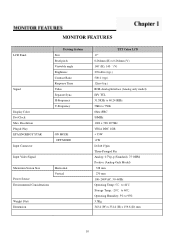
....) RGB Analog Interface (Analog only model) H/V TTL 31.5KHz to 60.241KHz 56Hz to 75Hz 6bits+FRC 80MHz 1024 x 768 @75Hz VESA DDC 1/2B < 35W MONITOR FEATURES LCD Panel Signal Display Color Dot Clock Max.
....) RGB Analog Interface (Analog only model) H/V TTL 31.5KHz to 60.241KHz 56Hz to 75Hz 6bits+FRC 80MHz 1024 x 768 @75Hz VESA DDC 1/2B < 35W MONITOR FEATURES LCD Panel Signal Display Color Dot Clock Max.
AL1706 Service Guide
Page 12
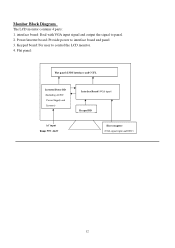
Monitor Block Diagram The LCD monitor contains 4 parts: 1. Keypad board: For user to panel. 2. Flat panel: Flat panel (LVDS interface) and CCFL Inverter/Power BD (Including AC/DC Power Supply and Inverter) Interface Board (VGA input) Keypad BD AC input Range 90V~264V Host computer (VGA signal input and DDC) 12 interface board: Deal with VGA input signal and output the signal to control the LCD monitor. 4. Power/inverter board: Provide power to interface board and panel 3.
Monitor Block Diagram The LCD monitor contains 4 parts: 1. Keypad board: For user to panel. 2. Flat panel: Flat panel (LVDS interface) and CCFL Inverter/Power BD (Including AC/DC Power Supply and Inverter) Interface Board (VGA input) Keypad BD AC input Range 90V~264V Host computer (VGA signal input and DDC) 12 interface board: Deal with VGA input signal and output the signal to control the LCD monitor. 4. Power/inverter board: Provide power to interface board and panel 3.
AL1706 Service Guide
Page 15
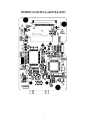
MONITOR INTERFACE BOARD PCB LAYOUT 15
MONITOR INTERFACE BOARD PCB LAYOUT 15
AL1706 Service Guide
Page 19
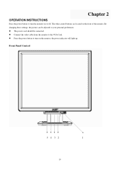
Connect the video cable from the monitor to your personal preferences. The power cord should be adjusted to the VGA Card. Chapter 2 OPERATION INSTRUCTIONS Press the power button to turn on the monitor, the power indicator will light up. The other control buttons are located on or off. Press the power button to turn the monitor on the front of the monitor. By changing these settings, the picture can be connected. Front Panel Control 5 4 3 2 1 19
Connect the video cable from the monitor to your personal preferences. The power cord should be adjusted to the VGA Card. Chapter 2 OPERATION INSTRUCTIONS Press the power button to turn on the monitor, the power indicator will light up. The other control buttons are located on or off. Press the power button to turn the monitor on the front of the monitor. By changing these settings, the picture can be connected. Front Panel Control 5 4 3 2 1 19
AL1706 Service Guide
Page 20
... When OSD menu is in a place subject to direct sunlight, or excessive dust or mechanical vibration or shock. NOTES Do not install the monitor in a location near heat sources such as radiators or air ducts, or in active status, this button will act as thinner, benzene, or...cloth lightly dampened with a soft cloth. Navigate through adjustments icons when OSD is activated. 1. For maximum protection, repackage your monitor. As a safety precaution, always unplug the monitor before cleaning it with a mild detergent solution. Off mode Activate OSD menu when OSD is in handy if you ever ...
... When OSD menu is in a place subject to direct sunlight, or excessive dust or mechanical vibration or shock. NOTES Do not install the monitor in a location near heat sources such as radiators or air ducts, or in active status, this button will act as thinner, benzene, or...cloth lightly dampened with a soft cloth. Navigate through adjustments icons when OSD is activated. 1. For maximum protection, repackage your monitor. As a safety precaution, always unplug the monitor before cleaning it with a mild detergent solution. Off mode Activate OSD menu when OSD is in handy if you ever ...
AL1706 Service Guide
Page 21
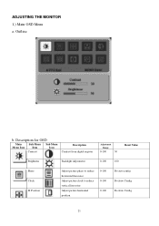
Description for OSD Main Sub Menu Sub Menu Menu Icon Item Icon Contrast Description Contrast from digital register Adjustment Range 0-100 50 Reset Value Brightness Backlight Adjustment 0-100 100 Phase Clock H. Position Adjust picture phase to reduce horizontal line noise Adjust picture clock to reduce vertical line noise Adjust picture horizontal position 0-100 0-100 0-100 Do auto config Do Auto Config Do Auto Config 21 Outline b. ADJUSTING THE MONITOR 1.) Main OSD Menu a.
Description for OSD Main Sub Menu Sub Menu Menu Icon Item Icon Contrast Description Contrast from digital register Adjustment Range 0-100 50 Reset Value Brightness Backlight Adjustment 0-100 100 Phase Clock H. Position Adjust picture phase to reduce horizontal line noise Adjust picture clock to reduce vertical line noise Adjust picture horizontal position 0-100 0-100 0-100 Do auto config Do Auto Config Do Auto Config 21 Outline b. ADJUSTING THE MONITOR 1.) Main OSD Menu a.
AL1706 Service Guide
Page 24
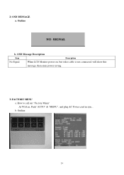
Outline b. Outline 24 b. 2) OSD MESSAGE a. OSD Message Description Item Description No Signal When LCD Monitor power on, but video cable is not connected, will show this message, then enter power saving. 3) FACTORY MENU a. How to call out "Factory Menu" At VGA in, Push "AUTO" & "MENU", and plug AC Power cord in sync..
Outline b. Outline 24 b. 2) OSD MESSAGE a. OSD Message Description Item Description No Signal When LCD Monitor power on, but video cable is not connected, will show this message, then enter power saving. 3) FACTORY MENU a. How to call out "Factory Menu" At VGA in, Push "AUTO" & "MENU", and plug AC Power cord in sync..
AL1706 Service Guide
Page 25
... defined in two levels, DDC1 and DDC2B. THIS MONITO WILL APPEAR TO BE NON-FUNCTIONAL IF THERE IS NO VIDEO INPUT SIGNAL. It allows the monitor to the VESA DDC STANDARD. The host can request EDID information over the DDC2B channel. HOW TO OPTIMIZE THE DOS-MODE PLUG AND PLAY Plug... power supply consumption. This feature is designed to an OFF mode. The DDC1 is no video input signal this monitor, following a time-out period, will automatically switch to conserve electrical energy by the Video Electronics Standards Association (VESA) and/or the United States Environmental Protection ...
... defined in two levels, DDC1 and DDC2B. THIS MONITO WILL APPEAR TO BE NON-FUNCTIONAL IF THERE IS NO VIDEO INPUT SIGNAL. It allows the monitor to the VESA DDC STANDARD. The host can request EDID information over the DDC2B channel. HOW TO OPTIMIZE THE DOS-MODE PLUG AND PLAY Plug... power supply consumption. This feature is designed to an OFF mode. The DDC1 is no video input signal this monitor, following a time-out period, will automatically switch to conserve electrical energy by the Video Electronics Standards Association (VESA) and/or the United States Environmental Protection ...
AL1706 Service Guide
Page 26
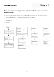
Therefore, lay the monitor on how to avoid mismatch when putting back the components. 2. The screws for maintenance ...soft surface when mounting or removing the base. 3. During the disassembly process, collect the screws with the corresponding components to assemble the monitor for the different components vary in size. Wear gloves Chassis*1 PCBA Power Board *1 INSULATOR PC,MYLAR SCREW (PW 3*6,M,ZN) *3 ...*1 Arm Stand*1 (M4x10,ZN)*4 Bracket Finger *1 Stand plate*1 Rubber*4 Hinge cover*1 Front bezel*1 Button*1 Indicator*1 26 The monitor surface is susceptible to scratching! NOTE: 1.
Therefore, lay the monitor on how to avoid mismatch when putting back the components. 2. The screws for maintenance ...soft surface when mounting or removing the base. 3. During the disassembly process, collect the screws with the corresponding components to assemble the monitor for the different components vary in size. Wear gloves Chassis*1 PCBA Power Board *1 INSULATOR PC,MYLAR SCREW (PW 3*6,M,ZN) *3 ...*1 Arm Stand*1 (M4x10,ZN)*4 Bracket Finger *1 Stand plate*1 Rubber*4 Hinge cover*1 Front bezel*1 Button*1 Indicator*1 26 The monitor surface is susceptible to scratching! NOTE: 1.
AL1706 User's Guide
Page 1
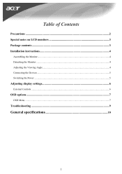
Table of Contents Precautions ...2 Special notes on LCD monitors 3 Package contents ...3 Installation instructions 4 Assembling the Monitor...4 Detaching the Monitor ...4 Adjusting the Viewing Angle...4 Connecting the Devices...5 Switching the Power ...5 Adjusting display settings 6 External Controls ...6 OSD options ...7 OSD Menu ...7 Troubleshooting ...9 General specifications 10 1
Table of Contents Precautions ...2 Special notes on LCD monitors 3 Package contents ...3 Installation instructions 4 Assembling the Monitor...4 Detaching the Monitor ...4 Adjusting the Viewing Angle...4 Connecting the Devices...5 Switching the Power ...5 Adjusting display settings 6 External Controls ...6 OSD options ...7 OSD Menu ...7 Troubleshooting ...9 General specifications 10 1
AL1706 User's Guide
Page 2
... us have healthier earth via appropriate treatment and recycling of industrial technology devices at the end-of heat. Recycling Information We, the Acer Incorporated. On the contrary, other hazards. We strongly encourage you to contact the provided information to avoid any danger of radiators, ... sprays. Be aware of the location of electrocution. When cleaning this product. Keep liquids away from the electric socket to recycle this monitor, disconnect it can lead to the unit. A cloth very slightly moistened with a mild detergent solution will be re-decomposed and re...
... us have healthier earth via appropriate treatment and recycling of industrial technology devices at the end-of heat. Recycling Information We, the Acer Incorporated. On the contrary, other hazards. We strongly encourage you to contact the provided information to avoid any danger of radiators, ... sprays. Be aware of the location of electrocution. When cleaning this product. Keep liquids away from the electric socket to recycle this monitor, disconnect it can lead to the unit. A cloth very slightly moistened with a mild detergent solution will be re-decomposed and re...
AL1706 User's Guide
Page 3
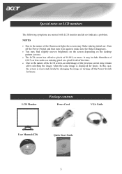
... the same image is recovered slowly by changing the image or turning off the Power Switch and then turn it on LCD monitors The following symptoms are normal with LCD monitor and do not indicate a problem. In this case, the screen is displayed for hours. NOTES • Due to the nature of... previous screen may find slightly uneven brightness on the screen depending on the desktop pattern you use . Turn off the Power Switch for hours. LCD Monitor Package contents Power Cord VGA Cable User Manual (CD) Quick Start Guide 3
... the same image is recovered slowly by changing the image or turning off the Power Switch and then turn it on LCD monitors The following symptoms are normal with LCD monitor and do not indicate a problem. In this case, the screen is displayed for hours. NOTES • Due to the nature of... previous screen may find slightly uneven brightness on the screen depending on the desktop pattern you use . Turn off the Power Switch for hours. LCD Monitor Package contents Power Cord VGA Cable User Manual (CD) Quick Start Guide 3
AL1706 User's Guide
Page 4
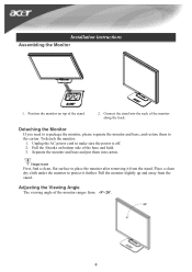
... to protect it from the stand. Pull the monitor slightly up and away from the stand. Connect the stand into carton. Place a clean dry cloth under the monitor to place the monitor after removing it further. To detach the monitor: 1. Adjusting the Viewing Angle The viewing angle ...of the base and hold. 3. Installation instructions Assembling the Monitor 1. Separate the monitor and base and put them to make sure ...
... to protect it from the stand. Pull the monitor slightly up and away from the stand. Connect the stand into carton. Place a clean dry cloth under the monitor to place the monitor after removing it further. To detach the monitor: 1. Adjusting the Viewing Angle The viewing angle ...of the base and hold. 3. Installation instructions Assembling the Monitor 1. Separate the monitor and base and put them to make sure ...
AL1706 User's Guide
Page 5
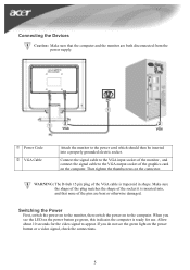
...signal to the power cord which should then be inserted into , and that the computer and the monitor are bent or otherwise damaged. When you do not see the LED on the computer. Allow about... 10 seconds for use. Power Code VGA Cable Attach the monitor to appear. WARNING: The D-Sub 15 pin plug of the graphics card on the power button go...pins are both disconnected from the power supply. Connect the signal cable to the VGA input socket of the monitor , and connect the signal cable to the computer. If you see the green light on the power button...
...signal to the power cord which should then be inserted into , and that the computer and the monitor are bent or otherwise damaged. When you do not see the LED on the computer. Allow about... 10 seconds for use. Power Code VGA Cable Attach the monitor to appear. WARNING: The D-Sub 15 pin plug of the graphics card on the power button go...pins are both disconnected from the power supply. Connect the signal cable to the VGA input socket of the monitor , and connect the signal cable to the computer. If you see the green light on the power button...
AL1706 User's Guide
Page 6
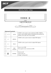
Power on/off 5 POWER Green: power on Orange: in sleep mode 6 Press to view OSD. 4 OSD Function Press again to exit a selection in OSD. Adjusting display settings External Controls 1 AUTO 2 < MINUS If OSD is active, press to enter a selection in OSD. If OSD is active, press to select or adjust OSD options. 3 > PLUS If OSD is inactive, press and the monitor will automatically optimize the position, focus and clock of your display. If OSD is active, press to select or adjust OSD options.
Power on/off 5 POWER Green: power on Orange: in sleep mode 6 Press to view OSD. 4 OSD Function Press again to exit a selection in OSD. Adjusting display settings External Controls 1 AUTO 2 < MINUS If OSD is active, press to enter a selection in OSD. If OSD is active, press to select or adjust OSD options. 3 > PLUS If OSD is inactive, press and the monitor will automatically optimize the position, focus and clock of your display. If OSD is active, press to select or adjust OSD options.
AL1706 User's Guide
Page 9
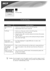
...if the problems cannot be causing interference. Picture shows • See "Color Adjustment" to adjust RGB color or to bring the monitor out of the monitor and the computer. • Move the mouse or press any key on the keyboard to select color inappropriate colors temperature. Troubleshooting ...connected. • Check to see if the power switch is in "Troubleshooting" section. 9 Image is present in the picture • Inspect the monitor's video cable and ensure that may be solved in the ON position. • Ensure that the Power Cord is connected. • Ensure the ...
...if the problems cannot be causing interference. Picture shows • See "Color Adjustment" to adjust RGB color or to bring the monitor out of the monitor and the computer. • Move the mouse or press any key on the keyboard to select color inappropriate colors temperature. Troubleshooting ...connected. • Check to see if the power switch is in "Troubleshooting" section. 9 Image is present in the picture • Inspect the monitor's video cable and ensure that may be solved in the ON position. • Ensure that the Power Cord is connected. • Ensure the ...


