

User Manual
Page 4
...1.3 Motherboard Layout 7 1.4 I/O Panel 9 Chapter 2 Installation 11 2.1 Installing the CPU 12 2.2 Installing the CPU Fan and Heatsink 15 2.3 Installing Memory Modules (DIMM) 16 2.4 Expansion Slots (PCI Express Slots) 18 2.5 Jumpers Setup 19 2.6 Onboard Headers and Connectors 20 2.7 Smart Switches 26 2.8 Dr. Debug 27 2.9 SLITM and Quad SLITM Operation Guide 29 2.9.1 Installing Two SLITM-Ready Graphics Cards 29 2.9.2 Driver Installation and Setup 31 2.10 CrossFireXTM and Quad CrossFireXTM Operation Guide 32 2.10.1 Installing Two CrossFireXTM-Ready Graphics Cards 32...
...1.3 Motherboard Layout 7 1.4 I/O Panel 9 Chapter 2 Installation 11 2.1 Installing the CPU 12 2.2 Installing the CPU Fan and Heatsink 15 2.3 Installing Memory Modules (DIMM) 16 2.4 Expansion Slots (PCI Express Slots) 18 2.5 Jumpers Setup 19 2.6 Onboard Headers and Connectors 20 2.7 Smart Switches 26 2.8 Dr. Debug 27 2.9 SLITM and Quad SLITM Operation Guide 29 2.9.1 Installing Two SLITM-Ready Graphics Cards 29 2.9.2 Driver Installation and Setup 31 2.10 CrossFireXTM and Quad CrossFireXTM Operation Guide 32 2.10.1 Installing Two CrossFireXTM-Ready Graphics Cards 32...
User Manual
Page 7
... about the model you for mini-PCIe Slot 1 English If you require technical support related to quality and endurance. Z97 Extreme6/3.1 Chapter 1 Introduction hank you are using. ASRock website http://www.asrock.com. 1.1 Package Contents • ASRock Z97 Extreme6/3.1 Motherboard (ATX Form Factor) • ASRock Z97 Extreme6/3.1 Quick Installation Guide • ASRock Z97 Extreme6/3.1 Support CD • 4 x Serial ATA (SATA) Data Cables (Optional) • 1 x I/O Panel Shield • 1 x ASRock USB 3.1/A+C • 1 x ASRock SLI_Bridge_2S Card • 1 x HDD Saver Cable •...
... about the model you for mini-PCIe Slot 1 English If you require technical support related to quality and endurance. Z97 Extreme6/3.1 Chapter 1 Introduction hank you are using. ASRock website http://www.asrock.com. 1.1 Package Contents • ASRock Z97 Extreme6/3.1 Motherboard (ATX Form Factor) • ASRock Z97 Extreme6/3.1 Quick Installation Guide • ASRock Z97 Extreme6/3.1 Support CD • 4 x Serial ATA (SATA) Data Cables (Optional) • 1 x I/O Panel Shield • 1 x ASRock USB 3.1/A+C • 1 x ASRock SLI_Bridge_2S Card • 1 x HDD Saver Cable •...

User Manual
Page 11
... PCI Express module up to Gen2 x2 (10 Gb/s) Connector • 1 x COM Port Header • 1 x TPM Header • 1 x Power LED Header • 2 x CPU Fan Connectors (1 x 4-pin, 1 x 3-pin) • 3 x Chassis Fan Connectors (1 x 4-pin, 2 x 3-pin) • 1 x Power Fan Connector (3-pin) • 1 x 24 pin ATX Power Connector • 1 x 8 pin 12V Power Connector (Hi-Density Power Connector) • 1 x HDD Saver Connector • 1 x PCIe Power Connector • 1 x Front Panel Audio Connector • 1 x hunderbolt AIC Connector • 2 x USB 2.0 Headers (support 4 USB 2.0 ports) (Supports...
... PCI Express module up to Gen2 x2 (10 Gb/s) Connector • 1 x COM Port Header • 1 x TPM Header • 1 x Power LED Header • 2 x CPU Fan Connectors (1 x 4-pin, 1 x 3-pin) • 3 x Chassis Fan Connectors (1 x 4-pin, 2 x 3-pin) • 1 x Power Fan Connector (3-pin) • 1 x 24 pin ATX Power Connector • 1 x 8 pin 12V Power Connector (Hi-Density Power Connector) • 1 x HDD Saver Connector • 1 x PCIe Power Connector • 1 x Front Panel Audio Connector • 1 x hunderbolt AIC Connector • 2 x USB 2.0 Headers (support 4 USB 2.0 ports) (Supports...

User Manual
Page 14
...) 6 Power Fan Connector (PWR_FAN1) 7 ATX Power Connector (ATXPWR1) 8 USB 3.0 Header (USB3_4_5) 9 Clear CMOS Jumper (CLRCMOS1) 10 SATA3 Connectors (SATA3_A3_A4) 11 SATA3 Connectors (SATA3_A1_A2) 12 SATA3 Connectors (SATA3_0_3) 13 SATA3 Connectors (SATA3_1_4) 14 SATA3 Connectors (SATA3_2_5) 15 SATA Express Connector (SATAE_1) 16 Chassis Fan Connector (CHA_FAN1) 17 Chassis Speaker Header (SPEAKER1) 18 Power LED Header (PLED1) 19 BIOS Selection Switch (BIOS_SEL1) 20 Power Switch (PWRBTN1) 21 Reset Switch (RSTBTN1) 22 HDD Saver Connector (SATA_PWR_1) 23 System Panel Header (PANEL1) 24 Vertical Type...
...) 6 Power Fan Connector (PWR_FAN1) 7 ATX Power Connector (ATXPWR1) 8 USB 3.0 Header (USB3_4_5) 9 Clear CMOS Jumper (CLRCMOS1) 10 SATA3 Connectors (SATA3_A3_A4) 11 SATA3 Connectors (SATA3_A1_A2) 12 SATA3 Connectors (SATA3_0_3) 13 SATA3 Connectors (SATA3_1_4) 14 SATA3 Connectors (SATA3_2_5) 15 SATA Express Connector (SATAE_1) 16 Chassis Fan Connector (CHA_FAN1) 17 Chassis Speaker Header (SPEAKER1) 18 Power LED Header (PLED1) 19 BIOS Selection Switch (BIOS_SEL1) 20 Power Switch (PWRBTN1) 21 Reset Switch (RSTBTN1) 22 HDD Saver Connector (SATA_PWR_1) 23 System Panel Header (PANEL1) 24 Vertical Type...

User Manual
Page 29
... GN D FAN_SPEED FAN_VOLTAGE GND 4 his motherboard pro- 3 2 vides a 4-Pin CPU fan 1 (Quiet Fan) connector. Please follow the instructions in the Realtek Control panel and adjust "Recording Volume". Connect Mic_IN (MIC) to Pin 1-3. D. C. GND FAN_VOLTAGE CHA_FAN_SPEED GND FAN_VOLTAGE CHA_FAN_SPEED CPU Fan Connectors (4-pin CPU_FAN1) (see p.7, No. 2) (3-pin CPU_FAN2) (see p.7, No. 6) GND +12V CHA_FAN_SPEED FAN_SPEED_CONTROL Please connect fan cables to the fan connectors and match the black wire to install your system. 2. Z97 Extreme6/3.1 1. E. MIC_RET and OUT_RET are...
... GN D FAN_SPEED FAN_VOLTAGE GND 4 his motherboard pro- 3 2 vides a 4-Pin CPU fan 1 (Quiet Fan) connector. Please follow the instructions in the Realtek Control panel and adjust "Recording Volume". Connect Mic_IN (MIC) to Pin 1-3. D. C. GND FAN_VOLTAGE CHA_FAN_SPEED GND FAN_VOLTAGE CHA_FAN_SPEED CPU Fan Connectors (4-pin CPU_FAN1) (see p.7, No. 2) (3-pin CPU_FAN2) (see p.7, No. 6) GND +12V CHA_FAN_SPEED FAN_SPEED_CONTROL Please connect fan cables to the fan connectors and match the black wire to install your system. 2. Z97 Extreme6/3.1 1. E. MIC_RET and OUT_RET are...

User Manual
Page 30
... p.7, No. 7) ATX 12V Power Connector (8-pin ATX12V1) (see p.7, No. 1) PCIe Power Connector (4-pin PCIE_PWR1) (see p.7, No. 30) HDD Saver Connector (4-pin SATA_PWR_1) (see p.7, No. 22) hunderbolt AIC Connector (5-pin TB1) (see p.7, No. 28) Serial Port Header (9-pin COM1) (see p.7, No. 31) 12 24 1 13 8 5 4 1 GND +12V DETECT 1 his COM1 header supports a serial port module. his motherboard provides an 8-pin ATX 12V power connector. Please connect a hunderbolt™ add-in card (AIC) to this connector when more than three PCI Express cards are installed.
... p.7, No. 7) ATX 12V Power Connector (8-pin ATX12V1) (see p.7, No. 1) PCIe Power Connector (4-pin PCIE_PWR1) (see p.7, No. 30) HDD Saver Connector (4-pin SATA_PWR_1) (see p.7, No. 22) hunderbolt AIC Connector (5-pin TB1) (see p.7, No. 28) Serial Port Header (9-pin COM1) (see p.7, No. 31) 12 24 1 13 8 5 4 1 GND +12V DETECT 1 his COM1 header supports a serial port module. his motherboard provides an 8-pin ATX 12V power connector. Please connect a hunderbolt™ add-in card (AIC) to this connector when more than three PCI Express cards are installed.
User Manual
Page 33
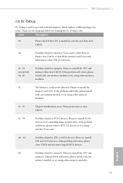
... using other devices. Please re-install IDE and SATA devices. Please re-install the CPU and memory. Code Description 00 Please check if the CPU is used to IDE or SATA devices. Please clear CMOS, re-install the memory and VGA card, and remove other USB, PCI devices. 01 - 54 (except 0d), 5A- 60 Problem related to memory, VGA card or other memory modules. 55 he Memory could not be detected. Please re-install PCI-E devices or try using another VGA card. Please press reset or clear CMOS. 92 - 99 Problem...
... using other devices. Please re-install IDE and SATA devices. Please re-install the CPU and memory. Code Description 00 Please check if the CPU is used to IDE or SATA devices. Please clear CMOS, re-install the memory and VGA card, and remove other USB, PCI devices. 01 - 54 (except 0d), 5A- 60 Problem related to memory, VGA card or other memory modules. 55 he Memory could not be detected. Please re-install PCI-E devices or try using another VGA card. Please press reset or clear CMOS. 92 - 99 Problem...

User Manual
Page 38
... this motherboard. If you to install up to PCIE4 slot. Make sure that your graphics card driver supports AMD CrossFireXTM technology. You should only use a AMD certiied PSU. Make sure that are supported with Windows® 7 / 7 64-bit / 8 / 8 64-bit / 8.1 / 8.1 64bit OS. 1. Please refer to the AMD's website for detailed installation guide. 2.10.1 Installing Two CrossFireXTM-Ready Graphics Cards Step 1 Insert one graphics card into PCIE2 slot and the other graphics card to three identical PCI Express x16 graphics cards...
... this motherboard. If you to install up to PCIE4 slot. Make sure that your graphics card driver supports AMD CrossFireXTM technology. You should only use a AMD certiied PSU. Make sure that are supported with Windows® 7 / 7 64-bit / 8 / 8 64-bit / 8.1 / 8.1 64bit OS. 1. Please refer to the AMD's website for detailed installation guide. 2.10.1 Installing Two CrossFireXTM-Ready Graphics Cards Step 1 Insert one graphics card into PCIE2 slot and the other graphics card to three identical PCI Express x16 graphics cards...
User Manual
Page 40
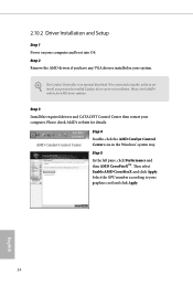
... AMD's website for AMD driver updates. Select the GPU number according to uninstall any VGA drivers installed in the Windows® system tray. Step 2 Remove the AMD drivers if you have any previously installed Catalyst drivers prior to installation. he Catalyst Uninstaller is an optional download. Please check AMD's website for details. hen select Enable AMD CrossFireX and click Apply. We recommend using this utility to your system. 2.10.2 Driver Installation and Setup Step 1 Power...
... AMD's website for AMD driver updates. Select the GPU number according to uninstall any VGA drivers installed in the Windows® system tray. Step 2 Remove the AMD drivers if you have any previously installed Catalyst drivers prior to installation. he Catalyst Uninstaller is an optional download. Please check AMD's website for details. hen select Enable AMD CrossFireX and click Apply. We recommend using this utility to your system. 2.10.2 Driver Installation and Setup Step 1 Power...
User Manual
Page 47
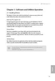
Z97 Extreme6/3.1 Chapter 3 Software and Utilities Operation 3.1 Installing Drivers he Support CD that comes with the motherboard contains necessary drivers and useful utilities that the motherboard supports. Running The Support CD To begin using the support CD, insert the CD into your computer. herefore, the drivers you install can work properly. "KB2720599": http://support.microsot.com/kb/2720599/en-us 41 English If the Main Menu does not appear automatically, locate and double click...
Z97 Extreme6/3.1 Chapter 3 Software and Utilities Operation 3.1 Installing Drivers he Support CD that comes with the motherboard contains necessary drivers and useful utilities that the motherboard supports. Running The Support CD To begin using the support CD, insert the CD into your computer. herefore, the drivers you install can work properly. "KB2720599": http://support.microsot.com/kb/2720599/en-us 41 English If the Main Menu does not appear automatically, locate and double click...
User Manual
Page 59
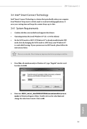
... Windows® sleep state to avoid loss. 1. Press Win + R simultaneously in Windows 8/7, type "Regedit" into 0. Double click on OK. 53 English Z97 Extreme6/3.1 3.4 Intel® Smart Connect Technology Intel® Smart Connect Technology is a feature that periodically wakes your computer from 3 into the word box then click OK. 2. or 64-bit edition) • Set the SATA mode to crash while booting. If Windows 8/7 is not in Windows Registry Editor. If your motherboard supports...
... Windows® sleep state to avoid loss. 1. Press Win + R simultaneously in Windows 8/7, type "Regedit" into 0. Double click on OK. 53 English Z97 Extreme6/3.1 3.4 Intel® Smart Connect Technology Intel® Smart Connect Technology is a feature that periodically wakes your computer from 3 into the word box then click OK. 2. or 64-bit edition) • Set the SATA mode to crash while booting. If Windows 8/7 is not in Windows Registry Editor. If your motherboard supports...

User Manual
Page 89
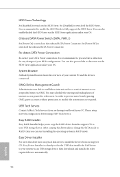
... installed. Onboard LAN2 Enable or disable the onboard network interface controller. Restore on . Good Night LED By enabling Good Night LED, the Power/HDD LEDs will be switched of when the system is on AC/Power Loss Select the power state ater a power failure. Render Standby Power down . It will also automatically switch of the Power and Keyboard LEDs when the system enters into Standby/Hibernation mode. Onboard HD Audio Enable/disable onboard HD audio. Front Panel Enable/disable front panel HD audio. If [Power Of] is installed. Z97 Extreme6...
... installed. Onboard LAN2 Enable or disable the onboard network interface controller. Restore on . Good Night LED By enabling Good Night LED, the Power/HDD LEDs will be switched of when the system is on AC/Power Loss Select the power state ater a power failure. Render Standby Power down . It will also automatically switch of the Power and Keyboard LEDs when the system enters into Standby/Hibernation mode. Onboard HD Audio Enable/disable onboard HD audio. Front Panel Enable/disable front panel HD audio. If [Power Of] is installed. Z97 Extreme6...

User Manual
Page 98
Set [Smart Auto] to keep the USB 3.0 driver enabled (Must install driver to disable legacy USB support. Set [Disabled] to support USB devices under the UEFI setup and Windows/Linux operating systems only. Select UEFI Setup Only to disable the USB 3.0 ports. Set [Auto] to automatically enable the USB 3.0 driver ater entering the OS (USB 3.0 is recommended to use USB devices under the UEFI setup and Windows/Linux operating systems only. 92 English Set [Enabled] to keep the USB 3.0 driver enabled ater rebooting (USB 3.0 is recommended to support USB devices under Windows&#...
Set [Smart Auto] to keep the USB 3.0 driver enabled (Must install driver to disable legacy USB support. Set [Disabled] to support USB devices under the UEFI setup and Windows/Linux operating systems only. Select UEFI Setup Only to disable the USB 3.0 ports. Set [Auto] to automatically enable the USB 3.0 driver ater entering the OS (USB 3.0 is recommended to use USB devices under the UEFI setup and Windows/Linux operating systems only. 92 English Set [Enabled] to keep the USB 3.0 driver enabled ater rebooting (USB 3.0 is recommended to support USB devices under Windows&#...
User Manual
Page 102
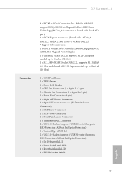
... application under your PC. Ater copying the drivers please change the SATA mode to RAID, then you can also enable/disable the HDD Saver via the HDD Saver application under your SATA Power connection. UEFI Tech Service Contact ASRock Tech Service if you to copy the RAID driver from our support CD, Easy Driver Installer is recommended to enable the AHCI Mode to your USB storage device. HDD Saver Technology Set [Enabled] to switch on the onboard SATA Power Connector. It is recommended to other required...
... application under your PC. Ater copying the drivers please change the SATA mode to RAID, then you can also enable/disable the HDD Saver via the HDD Saver application under your SATA Power connection. UEFI Tech Service Contact ASRock Tech Service if you to copy the RAID driver from our support CD, Easy Driver Installer is recommended to enable the AHCI Mode to your USB storage device. HDD Saver Technology Set [Enabled] to switch on the onboard SATA Power Connector. It is recommended to other required...

User Manual
Page 103
... the current working ROM image to download the UEFI irmware. 97 English Network Coniguration Use this function. UEFI Download Server Select a server to the secondary lash ROM. Z97 Extreme6/3.1 Instant Flash Save UEFI iles in your USB storage device and run Instant Flash to update your USB pen drive before using this to conigure internet connection settings for you. Please setup network coniguration before using Internet Flash. *For BIOS backup and recovery purpose, it is recommended to plug in the setup utility.
... the current working ROM image to download the UEFI irmware. 97 English Network Coniguration Use this function. UEFI Download Server Select a server to the secondary lash ROM. Z97 Extreme6/3.1 Instant Flash Save UEFI iles in your USB storage device and run Instant Flash to update your USB pen drive before using this to conigure internet connection settings for you. Please setup network coniguration before using Internet Flash. *For BIOS backup and recovery purpose, it is recommended to plug in the setup utility.

Quick Installation Guide
Page 4
...) 6 Power Fan Connector (PWR_FAN1) 7 ATX Power Connector (ATXPWR1) 8 USB 3.0 Header (USB3_4_5) 9 Clear CMOS Jumper (CLRCMOS1) 10 SATA3 Connectors (SATA3_A3_A4) 11 SATA3 Connectors (SATA3_A1_A2) 12 SATA3 Connectors (SATA3_0_3) 13 SATA3 Connectors (SATA3_1_4) 14 SATA3 Connectors (SATA3_2_5) 15 SATA Express Connector (SATAE_1) 16 Chassis Fan Connector (CHA_FAN1) 17 Chassis Speaker Header (SPEAKER1) 18 Power LED Header (PLED1) 19 BIOS Selection Switch (BIOS_SEL1) 20 Power Switch (PWRBTN1) 21 Reset Switch (RSTBTN1) 22 HDD Saver Connector (SATA_PWR_1) 23 System Panel Header (PANEL1) 24 Vertical Type...
...) 6 Power Fan Connector (PWR_FAN1) 7 ATX Power Connector (ATXPWR1) 8 USB 3.0 Header (USB3_4_5) 9 Clear CMOS Jumper (CLRCMOS1) 10 SATA3 Connectors (SATA3_A3_A4) 11 SATA3 Connectors (SATA3_A1_A2) 12 SATA3 Connectors (SATA3_0_3) 13 SATA3 Connectors (SATA3_1_4) 14 SATA3 Connectors (SATA3_2_5) 15 SATA Express Connector (SATAE_1) 16 Chassis Fan Connector (CHA_FAN1) 17 Chassis Speaker Header (SPEAKER1) 18 Power LED Header (PLED1) 19 BIOS Selection Switch (BIOS_SEL1) 20 Power Switch (PWRBTN1) 21 Reset Switch (RSTBTN1) 22 HDD Saver Connector (SATA_PWR_1) 23 System Panel Header (PANEL1) 24 Vertical Type...
Quick Installation Guide
Page 11
... and M.2 PCI Express module up to Gen2 x2 (10 Gb/s) • 1 x COM Port Header • 1 x TPM Header • 1 x Power LED Header • 2 x CPU Fan Connectors (1 x 4-pin, 1 x 3-pin) • 3 x Chassis Fan Connectors (1 x 4-pin, 2 x 3-pin) • 1 x Power Fan Connector (3-pin) • 1 x 24 pin ATX Power Connector • 1 x 8 pin 12V Power Connector (Hi-Density Power Connector) • 1 x HDD Saver Connector • 1 x PCIe Power Connector • 1 x Front Panel Audio Connector • 1 x hunderbolt AIC Connector • 2 x USB 2.0 Headers (support 4 USB 2.0 ports) (Supports ESD...
... and M.2 PCI Express module up to Gen2 x2 (10 Gb/s) • 1 x COM Port Header • 1 x TPM Header • 1 x Power LED Header • 2 x CPU Fan Connectors (1 x 4-pin, 1 x 3-pin) • 3 x Chassis Fan Connectors (1 x 4-pin, 2 x 3-pin) • 1 x Power Fan Connector (3-pin) • 1 x 24 pin ATX Power Connector • 1 x 8 pin 12V Power Connector (Hi-Density Power Connector) • 1 x HDD Saver Connector • 1 x PCIe Power Connector • 1 x Front Panel Audio Connector • 1 x hunderbolt AIC Connector • 2 x USB 2.0 Headers (support 4 USB 2.0 ports) (Supports ESD...

Quick Installation Guide
Page 25
Z97 Extreme6/3.1 1. C. D. To activate the front mic, go to the ground pin. MIC_RET and OUT_RET are for the AC'97 audio panel. Chassis and Power Fan Connectors (4-pin CHA_FAN1) (see p.1, No. 16) (3-pin CHA_FAN2) (see p.1, No. 29) (3-pin CHA_FAN3) (see p.1, No. 34) (3-pin PWR_FAN1) (see p.1, No. 3) FAN_SPEED_CONTROL FAN_SPEED + 12V GN D FAN_SPEED FAN_VOLTAGE GND 4 his motherboard pro- 3 2 vides a 4-Pin CPU fan 1 (Quiet Fan) connector. If you use an AC'97 audio panel, please install it to...
Z97 Extreme6/3.1 1. C. D. To activate the front mic, go to the ground pin. MIC_RET and OUT_RET are for the AC'97 audio panel. Chassis and Power Fan Connectors (4-pin CHA_FAN1) (see p.1, No. 16) (3-pin CHA_FAN2) (see p.1, No. 29) (3-pin CHA_FAN3) (see p.1, No. 34) (3-pin PWR_FAN1) (see p.1, No. 3) FAN_SPEED_CONTROL FAN_SPEED + 12V GN D FAN_SPEED FAN_VOLTAGE GND 4 his motherboard pro- 3 2 vides a 4-Pin CPU fan 1 (Quiet Fan) connector. If you use an AC'97 audio panel, please install it to...

Quick Installation Guide
Page 26
...#1 his motherboard provides an 8-pin ATX 12V power connector. To use a 4-pin ATX power supply, please plug it along Pin 1 and Pin 5. Please connect a 4 pin molex power cable to this connector to manage the power state of HDD. Please connect the HDD Saver Cable to this connector via the GPIO cable. his COM1 header supports a serial port module. Please connect a hunderbolt™ add-in card (AIC) to this connector when more than three graphics cards are installed. English 24 ATX Power Connector (24-pin ATXPWR1) (see p.1, No. 7) ATX 12V Power Connector (8-pin ATX12V1...
...#1 his motherboard provides an 8-pin ATX 12V power connector. To use a 4-pin ATX power supply, please plug it along Pin 1 and Pin 5. Please connect a 4 pin molex power cable to this connector to manage the power state of HDD. Please connect the HDD Saver Cable to this connector via the GPIO cable. his COM1 header supports a serial port module. Please connect a hunderbolt™ add-in card (AIC) to this connector when more than three graphics cards are installed. English 24 ATX Power Connector (24-pin ATXPWR1) (see p.1, No. 7) ATX 12V Power Connector (8-pin ATX12V1...

Quick Installation Guide
Page 29
Z97 Extreme6/3.1 2.8 Dr. Debug Dr. Debug is installed correctly and then clear CMOS. 0d Problem related to memory, VGA card or other slots. Please see the diagrams below for reading the Dr. Debug codes. Please re-install the CPU and memory then clear CMOS. Please re-install PCI-E devices or try using another VGA card. Code Description 00 Please check if the CPU is used to PCI-E devices. If the problem still exists, please install only one memory module or try installing them...
Z97 Extreme6/3.1 2.8 Dr. Debug Dr. Debug is installed correctly and then clear CMOS. 0d Problem related to memory, VGA card or other slots. Please see the diagrams below for reading the Dr. Debug codes. Please re-install the CPU and memory then clear CMOS. Please re-install PCI-E devices or try using another VGA card. Code Description 00 Please check if the CPU is used to PCI-E devices. If the problem still exists, please install only one memory module or try installing them...


