
User Manual
Page 7
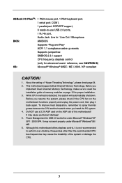
... Dual Channel Memory Technology, make sure to read the installation guide of memory modules on page 12 for USB 2.0 works fine under Microsoft® Windows® 98 / ME. 6. Frequencies other than the recommended CPU bus frequencies may cause the instability of "Hyper Threading Technology", please check page 24. 2. ASRock I/O PlusTM: 1 PS/2 mouse port, 1 PS/2 keyboard port, 1 serial port: COM1, 1 parallel port: ECP/EPP support, 6 ready-to-use a 3.3V AGP card on the AGP slot of this motherboard...
... Dual Channel Memory Technology, make sure to read the installation guide of memory modules on page 12 for USB 2.0 works fine under Microsoft® Windows® 98 / ME. 6. Frequencies other than the recommended CPU bus frequencies may cause the instability of "Hyper Threading Technology", please check page 24. 2. ASRock I/O PlusTM: 1 PS/2 mouse port, 1 PS/2 keyboard port, 1 serial port: COM1, 1 parallel port: ECP/EPP support, 6 ready-to-use a 3.3V AGP card on the AGP slot of this motherboard...

User Manual
Page 8
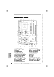
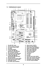
... 5 x PCI Slots (PCI1- 5) 24 Flash Memory 25 JL1 Jumper 26 JR1 Jumper 27 Front Panel Audio Header (AUDIO1) 28 Internal Audio Connector: AUX1 (White) 29 Internal Audio Connector: CD1 (Black) 30 Shared USB 2.0 Header (USB4_5, Blue) 31 ATX Power Connector (ATXPWR1) 8 Blue) 7 ATX 12V Connector (ATX12V1) 8 Secondary IDE Connector (IDE2, Black) 9 Primary IDE Connector (IDE1, Blue) 10 2 x 184-pin DDR DIMM Slots (Dual Channel B: DDR2, DDR4; 1.3 Motherboard Layout 12 3 45 21.8cm (8.6 in) 67 PS2 Mouse 1 PS2_USB_PWR1 CPU_FAN1 PS2 Keyboard ATX12V1 PARALLEL PORT COM1...
... 5 x PCI Slots (PCI1- 5) 24 Flash Memory 25 JL1 Jumper 26 JR1 Jumper 27 Front Panel Audio Header (AUDIO1) 28 Internal Audio Connector: AUX1 (White) 29 Internal Audio Connector: CD1 (Black) 30 Shared USB 2.0 Header (USB4_5, Blue) 31 ATX Power Connector (ATXPWR1) 8 Blue) 7 ATX 12V Connector (ATX12V1) 8 Secondary IDE Connector (IDE2, Black) 9 Primary IDE Connector (IDE1, Blue) 10 2 x 184-pin DDR DIMM Slots (Dual Channel B: DDR2, DDR4; 1.3 Motherboard Layout 12 3 45 21.8cm (8.6 in) 67 PS2 Mouse 1 PS2_USB_PWR1 CPU_FAN1 PS2 Keyboard ATX12V1 PARALLEL PORT COM1...
User Manual
Page 24
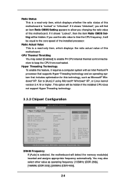
... Value This is selected, the motherboard will be hidden if the installed CPU does not support Hyper-Threading technology. 3.3.2 Chipset Configuration BIOS SETUP UTILITY Advanced Chipset Configuration DRAM Frequency Flexibility Option DRAM CAS# Latency DRAM Command Rate DRAM Bus Selection [Auto] [Disabled] [Auto] [2T Command] [Auto] DRAM Voltage AGP Voltage [Normal] [High] Primary Graphics Adapter AGP Aperture Size AGP Mode AGP Fast Write [PCI] [64MB] [Auto] [Disabled] PCI Delay Transaction OnBoard LAN OnBoard AC'97 Audio [Disabled] [Eabled] [Auto] Options 133MHz 166MHz 200MHz...
... Value This is selected, the motherboard will be hidden if the installed CPU does not support Hyper-Threading technology. 3.3.2 Chipset Configuration BIOS SETUP UTILITY Advanced Chipset Configuration DRAM Frequency Flexibility Option DRAM CAS# Latency DRAM Command Rate DRAM Bus Selection [Auto] [Disabled] [Auto] [2T Command] [Auto] DRAM Voltage AGP Voltage [Normal] [High] Primary Graphics Adapter AGP Aperture Size AGP Mode AGP Fast Write [PCI] [64MB] [Auto] [Disabled] PCI Delay Transaction OnBoard LAN OnBoard AC'97 Audio [Disabled] [Eabled] [Auto] Options 133MHz 166MHz 200MHz...
User Manual
Page 27
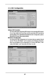
...DISABLED: disables the integrated IDE Controller. SECONDARY: enables only the Secondary IDE Controller. Set to [Disabled] will use the "Primary IDE Master" as well. BOTH: enables both . Advanced BIOS SETUP UTILITY Primary IDE Master Device Vendor Size LBA Mode Block Mode PIO Mode Async DMA Ultra DMA S.M.A.R.T. Type LBA/Large Mode Block (Multi-Sector Transfer) PIO Mode DMA Mode S.M.A.R.T. 32Bit Data Transfer :Hard Disk :ST340014A :40.0 GB :Supported :16Sectors :4 :MultiWord DMA-2 :Ultra DMA-5 :Supported [Auto] [Auto] [Auto] [Auto] [Auto] [Disabled] [Disabled] Select the type...
...DISABLED: disables the integrated IDE Controller. SECONDARY: enables only the Secondary IDE Controller. Set to [Disabled] will use the "Primary IDE Master" as well. BOTH: enables both . Advanced BIOS SETUP UTILITY Primary IDE Master Device Vendor Size LBA Mode Block Mode PIO Mode Async DMA Ultra DMA S.M.A.R.T. Type LBA/Large Mode Block (Multi-Sector Transfer) PIO Mode DMA Mode S.M.A.R.T. 32Bit Data Transfer :Hard Disk :ST340014A :40.0 GB :Supported :16Sectors :4 :MultiWord DMA-2 :Ultra DMA-5 :Supported [Auto] [Auto] [Auto] [Auto] [Auto] [Disabled] [Disabled] Select the type...
User Manual
Page 28
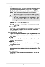
... enhance hard disk performance by optimizing the hard disk timing. If this feature is [Auto]. After selecting the hard disk information into BIOS, use of IDE device. [Auto]: Select [Auto] to automatically detect the hard disk drive. PIO Mode Use this item to set the partition of the Primary IDE hard disk drives to active. [CD/DVD]: This is used for compatible IDE devices. Configuration options: [Disabled], [Auto], [Enabled]. 32-Bit Data Transfer Use this item to enable or disable the S.M.A.R.T. (Self-Monitoring, Analysis, and Reporting Technology) feature. for a hard disk...
... enhance hard disk performance by optimizing the hard disk timing. If this feature is [Auto]. After selecting the hard disk information into BIOS, use of IDE device. [Auto]: Select [Auto] to automatically detect the hard disk drive. PIO Mode Use this item to set the partition of the Primary IDE hard disk drives to active. [CD/DVD]: This is used for compatible IDE devices. Configuration options: [Disabled], [Auto], [Enabled]. 32-Bit Data Transfer Use this item to enable or disable the S.M.A.R.T. (Self-Monitoring, Analysis, and Reporting Technology) feature. for a hard disk...
User Manual
Page 30
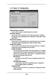
... Use this item to set the address for the parallel port. The default value is set the IRQ for the onboard parallel port or disable it . Configuration options: [DMA0], [DMA1], and [DMA3]. Configuration options: [IRQ5] and [IRQ7]. 30 Configuration options: [Disabled], [378], and [278]. 3.3.7 Super IO Configuration Advanced BIOS SETUP UTILITY Configure Super IO Chipset OnBoard Floppy Controller Serial Port Address Infrared Port Address Parallel Port Address Parallel Port Mode EPP Version ECP Mode DMA Channel Parallel Port IRQ OnBoard Game Port OnBoard MIDI Port [Enabled...
... Use this item to set the address for the parallel port. The default value is set the IRQ for the onboard parallel port or disable it . Configuration options: [DMA0], [DMA1], and [DMA3]. Configuration options: [IRQ5] and [IRQ7]. 30 Configuration options: [Disabled], [378], and [278]. 3.3.7 Super IO Configuration Advanced BIOS SETUP UTILITY Configure Super IO Chipset OnBoard Floppy Controller Serial Port Address Infrared Port Address Parallel Port Address Parallel Port Mode EPP Version ECP Mode DMA Channel Parallel Port IRQ OnBoard Game Port OnBoard MIDI Port [Enabled...
User Manual
Page 31
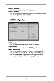
... disable the support to emulate legacy I/O devices such as mouse, keyboard,... USB 2.0 Support Use this item to auto-detect; etc. OnBoard MIDI Port Use this itme to select the address for the MIDI Port or disable it . Configuration options: [Disabled], [300], and [330]. 3.3.8 USB Configuration Advanced BIOS SETUP UTILITY USB Configuration USB Devices Enabled : None USB Controller USB 2.0 Support Legacy USB Support [Enabled] [Enabled] [Disabled] To enable or disable the onboard USB controllers. +F1 F9 F10 ESC Select Screen Select Item Change Option General Help Load Defaults...
... disable the support to emulate legacy I/O devices such as mouse, keyboard,... USB 2.0 Support Use this item to auto-detect; etc. OnBoard MIDI Port Use this itme to select the address for the MIDI Port or disable it . Configuration options: [Disabled], [300], and [330]. 3.3.8 USB Configuration Advanced BIOS SETUP UTILITY USB Configuration USB Devices Enabled : None USB Controller USB 2.0 Support Legacy USB Support [Enabled] [Enabled] [Disabled] To enable or disable the onboard USB controllers. +F1 F9 F10 ESC Select Screen Select Item Change Option General Help Load Defaults...
User Manual
Page 33
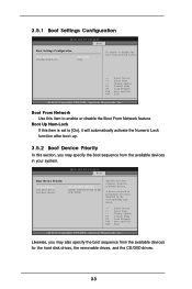
... hard disk drives, the removable drives, and the CD/DVD drives. 33 BIOS SETUP UTILITY Boot Boot Device Priority 1st Boot Device 2nd Boot Device 3rd Boot Device [1st FLOPPY DRIVE] [HDD: PM-MAXTOR 6L08] [CD / DVD] Specifies the boot sequence from network feature. +F1 F9 F10 ESC Select Screen Select Item Change Option General Help Load Defaults Save and Exit Exit v02.54 (C) Copyright 1985-2003, American Megatrends, Inc. A device enclosed in parenthesis has been disabled in your system. 3.5.1 Boot Settings Configuration BIOS SETUP UTILITY Boot Boot Settings Configuration Boot...
... hard disk drives, the removable drives, and the CD/DVD drives. 33 BIOS SETUP UTILITY Boot Boot Device Priority 1st Boot Device 2nd Boot Device 3rd Boot Device [1st FLOPPY DRIVE] [HDD: PM-MAXTOR 6L08] [CD / DVD] Specifies the boot sequence from network feature. +F1 F9 F10 ESC Select Screen Select Item Change Option General Help Load Defaults Save and Exit Exit v02.54 (C) Copyright 1985-2003, American Megatrends, Inc. A device enclosed in parenthesis has been disabled in your system. 3.5.1 Boot Settings Configuration BIOS SETUP UTILITY Boot Boot Settings Configuration Boot...
User Manual
Page 36
... ASRock's website at http://www.asrock.com; Refer to display the menus. 4.2.2 Drivers Menu The Drivers Menu shows the available devices drivers if the system detects installed devices. The CD automatically displays the Main Menu if "AUTORUN" is enabled in your CD-ROM drive. Please install the necessary drivers to know more information. 4.2 Support CD Information The Support CD that came with the motherboard contains necessary drivers and useful utilities that the motherboard supports. 4. Click on the file...
... ASRock's website at http://www.asrock.com; Refer to display the menus. 4.2.2 Drivers Menu The Drivers Menu shows the available devices drivers if the system detects installed devices. The CD automatically displays the Main Menu if "AUTORUN" is enabled in your CD-ROM drive. Please install the necessary drivers to know more information. 4.2 Support CD Information The Support CD that came with the motherboard contains necessary drivers and useful utilities that the motherboard supports. 4. Click on the file...
Quick Installation Guide
Page 2
...) 20 USB 2.0 Header (USB67, Blue) 21 Infrared Module Header (IR1) 22 Game Connector (GAME1) 23 5 x PCI Slots (PCI1- 5) 24 Flash Memory 25 JL1 Jumper 26 JR1 Jumper 27 Front Panel Audio Header (AUDIO1) 28 Internal Audio Connector: AUX1 (White) 29 Internal Audio Connector: CD1 (Black) 30 Shared USB 2.0 Header (USB4_5, Blue) 31 ATX Power Connector (ATXPWR1) 2 ASRock P4V88/P4V88+ Motherboard Motherboard Layout English 1 PS2_USB_PWR1 Jumper 2 CPU Fan Connector (CPU_FAN1) 3 CPU Heatsink Retention Module 4 CPU Socket 5 North Bridge Controller 6 2 x 184-pin DDR DIMM Slots (Dual Channel A: DDR1...
...) 20 USB 2.0 Header (USB67, Blue) 21 Infrared Module Header (IR1) 22 Game Connector (GAME1) 23 5 x PCI Slots (PCI1- 5) 24 Flash Memory 25 JL1 Jumper 26 JR1 Jumper 27 Front Panel Audio Header (AUDIO1) 28 Internal Audio Connector: AUX1 (White) 29 Internal Audio Connector: CD1 (Black) 30 Shared USB 2.0 Header (USB4_5, Blue) 31 ATX Power Connector (ATXPWR1) 2 ASRock P4V88/P4V88+ Motherboard Motherboard Layout English 1 PS2_USB_PWR1 Jumper 2 CPU Fan Connector (CPU_FAN1) 3 CPU Heatsink Retention Module 4 CPU Socket 5 North Bridge Controller 6 2 x 184-pin DDR DIMM Slots (Dual Channel A: DDR1...
Quick Installation Guide
Page 13
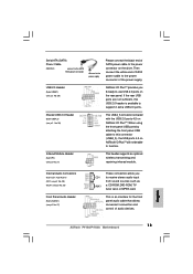
... panel USB cable to receive stereo audio input from sound sources such as a CD-ROM, DVD-ROM, TV tuner card, or MPEG card. English 13 ASRock P4V88/P4V88+ Motherboard If the rear USB ports are not sufficient, this connector (USB4_5), the USB ports 4,5 on the rear panel. USB 2.0 Header (9-pin USB67) (see p.2 No. 30) This USB4_5 connector is an interface for the front panel audio cable that allows convenient connection and control of SATA power cable to -use USB 2.0 ports on ASRock I /O PlusTM. Serial ATA (SATA) Power Cable (Optional) connect to the SATA HDD power connector...
... panel USB cable to receive stereo audio input from sound sources such as a CD-ROM, DVD-ROM, TV tuner card, or MPEG card. English 13 ASRock P4V88/P4V88+ Motherboard If the rear USB ports are not sufficient, this connector (USB4_5), the USB ports 4,5 on the rear panel. USB 2.0 Header (9-pin USB67) (see p.2 No. 30) This USB4_5 connector is an interface for the front panel audio cable that allows convenient connection and control of SATA power cable to -use USB 2.0 ports on ASRock I /O PlusTM. Serial ATA (SATA) Power Cable (Optional) connect to the SATA HDD power connector...
Quick Installation Guide
Page 14
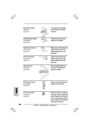
... panel functions. English ATX Power Connector (20-pin ATXPWR1) (see p.2 No. 31) Please connect an ATX power supply to this connector and match the black wire to this connector. Failing to do so will cause the failure to this connector so that it is installed. Please connect the CPU fan cable to the ground pin. Connect a Game cable to this connector if the Game port bracket is necessary to connect a power supply with ATX 12V plug to power up. 14 ASRock P4V88/P4V88+ Motherboard...
... panel functions. English ATX Power Connector (20-pin ATXPWR1) (see p.2 No. 31) Please connect an ATX power supply to this connector and match the black wire to this connector. Failing to do so will cause the failure to this connector so that it is installed. Please connect the CPU fan cable to the ground pin. Connect a Game cable to this connector if the Game port bracket is necessary to connect a power supply with ATX 12V plug to power up. 14 ASRock P4V88/P4V88+ Motherboard...
Quick Installation Guide
Page 16
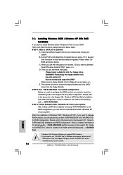
... ASRock P4V88/P4V88+ Motherboard English E. The system will lose ALL data in the folder at the following path: .. \ VIA RAID Tool 1. After the installation of system boot-up, press key,and then a window for RAID configuration. A. C. Before you start to install Windows 2000 / Windows XP on your system. Please refer to the document in the Support CD, "Guide to SATA Hard Disks Installation and RAID Configuration", which is located in Windows environment, please install SATA drivers from the Support...
... ASRock P4V88/P4V88+ Motherboard English E. The system will lose ALL data in the folder at the following path: .. \ VIA RAID Tool 1. After the installation of system boot-up, press key,and then a window for RAID configuration. A. C. Before you start to install Windows 2000 / Windows XP on your system. Please refer to the document in the Support CD, "Guide to SATA Hard Disks Installation and RAID Configuration", which is located in Windows environment, please install SATA drivers from the Support...
Quick Installation Guide
Page 18
... the Main Menu does not appear automatically, locate and double-click on the file "ASSETUP.EXE" from the BIN folder in your CD-ROM drive. otherwise, POST continues with the motherboard contains necessary drivers and useful utilities that came with its various sub-menus and to the User Manual (PDF file) contained in the Support CD. 4. If you start up the computer, please press during the Power-On...
... the Main Menu does not appear automatically, locate and double-click on the file "ASSETUP.EXE" from the BIN folder in your CD-ROM drive. otherwise, POST continues with the motherboard contains necessary drivers and useful utilities that came with its various sub-menus and to the User Manual (PDF file) contained in the Support CD. 4. If you start up the computer, please press during the Power-On...
User Manual
Page 8
... JL1 Audio CODEC LAN PHY VPIACT8h8ip0seAtGP 8X 1.5V_AGP1 PCI 1 IDE1 SATA2 Super I/O 2MB BIOS GAME1 PCI 2 USB2.0 FSB800 DDR400 PCI 3 5.1 CH PCI 4 ATA133 SATA PCI 5 1 IR1 P4V88 VIA VT8237 CMOS Battery CLRCMOS1 FLOPPY1 SATA1 USB67 1 CHA_FAN1 SPEAKER1 1 PANEL 1 PLED PWRBTN 1 HDLED RESET 9 10 11 12 13 14 15 16 22 21 20 19 18 17 1 PS2_USB_PWR1 Jumper 2 CPU Fan Connector (CPU_FAN1) 3 CPU Heatsink Retention Module 4 CPU Socket 5 North Bridge Controller 6 2 x 184-pin DDR DIMM Slots (Dual Channel...
... JL1 Audio CODEC LAN PHY VPIACT8h8ip0seAtGP 8X 1.5V_AGP1 PCI 1 IDE1 SATA2 Super I/O 2MB BIOS GAME1 PCI 2 USB2.0 FSB800 DDR400 PCI 3 5.1 CH PCI 4 ATA133 SATA PCI 5 1 IR1 P4V88 VIA VT8237 CMOS Battery CLRCMOS1 FLOPPY1 SATA1 USB67 1 CHA_FAN1 SPEAKER1 1 PANEL 1 PLED PWRBTN 1 HDLED RESET 9 10 11 12 13 14 15 16 22 21 20 19 18 17 1 PS2_USB_PWR1 Jumper 2 CPU Fan Connector (CPU_FAN1) 3 CPU Heatsink Retention Module 4 CPU Socket 5 North Bridge Controller 6 2 x 184-pin DDR DIMM Slots (Dual Channel...

User Manual
Page 27
...) PIO Mode DMA Mode S.M.A.R.T. 32Bit Data Transfer :Hard Disk :ST340014A :40.0 GB :Supported :16Sectors :4 :MultiWord DMA-2 :Ultra DMA-5 :Supported [Auto] [Auto] [Auto] [Auto] [Auto] [Disabled] [Disabled] Select the type of "Primary IDE Slave", "Secondary IDE Master", and "Secondary IDE Slave" as the example in the following instruction, which can be applied to the configurations of device connected to [Disabled] will use the "Primary IDE Master" as well. 3.3.4 IDE Configuration Advanced BIOS SETUP UTILITY IDE Configuration OnBoard IDE Controller Primary IDE Master Primary IDE Slave...
...) PIO Mode DMA Mode S.M.A.R.T. 32Bit Data Transfer :Hard Disk :ST340014A :40.0 GB :Supported :16Sectors :4 :MultiWord DMA-2 :Ultra DMA-5 :Supported [Auto] [Auto] [Auto] [Auto] [Auto] [Disabled] [Disabled] Select the type of "Primary IDE Slave", "Secondary IDE Master", and "Secondary IDE Slave" as the example in the following instruction, which can be applied to the configurations of device connected to [Disabled] will use the "Primary IDE Master" as well. 3.3.4 IDE Configuration Advanced BIOS SETUP UTILITY IDE Configuration OnBoard IDE Controller Primary IDE Master Primary IDE Slave...
User Manual
Page 28
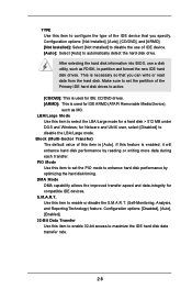
.../Large mode. Configuration options: [Not Installed], [Auto], [CD/DVD], and [ARMD]. [Not Installed]: Select [Not Installed] to disable the use a disk utility, such as MO. for compatible IDE devices. Configuration options: [Disabled], [Auto], [Enabled]. 32-Bit Data Transfer Use this item to select the LBA/Large mode for IDE ARMD (ATAPI Removable Media Device), such as FDISK, to automatically detect the hard disk drive. TYPE Use this item to set the partition of the Primary IDE hard disk drives to active. [CD/DVD]: This is used for IDE CD/DVD drives...
.../Large mode. Configuration options: [Not Installed], [Auto], [CD/DVD], and [ARMD]. [Not Installed]: Select [Not Installed] to disable the use a disk utility, such as MO. for compatible IDE devices. Configuration options: [Disabled], [Auto], [Enabled]. 32-Bit Data Transfer Use this item to select the LBA/Large mode for IDE ARMD (ATAPI Removable Media Device), such as FDISK, to automatically detect the hard disk drive. TYPE Use this item to set the partition of the Primary IDE hard disk drives to active. [CD/DVD]: This is used for IDE CD/DVD drives...

User Manual
Page 30
... Use this item to set the address for the onboard serial port or disable it . 3.3.7 Super IO Configuration Advanced BIOS SETUP UTILITY Configure Super IO Chipset OnBoard Floppy Controller Serial Port Address Infrared Port Address Parallel Port Address Parallel Port Mode EPP Version ECP Mode DMA Channel Parallel Port IRQ OnBoard Game Port OnBoard MIDI Port [Enabled] [3F8 / IRQ4] [Disabled] [378] [ECP + EPP] [1.9] [DMA3] [IRQ7] [Enabled] [Disabled] Allow BIOS to set the operation mode of the parallel port. The default value is set the ECP mode DMA channel. Configuration options...
... Use this item to set the address for the onboard serial port or disable it . 3.3.7 Super IO Configuration Advanced BIOS SETUP UTILITY Configure Super IO Chipset OnBoard Floppy Controller Serial Port Address Infrared Port Address Parallel Port Address Parallel Port Mode EPP Version ECP Mode DMA Channel Parallel Port IRQ OnBoard Game Port OnBoard MIDI Port [Enabled] [3F8 / IRQ4] [Disabled] [378] [ECP + EPP] [1.9] [DMA3] [IRQ7] [Enabled] [Disabled] Allow BIOS to set the operation mode of the parallel port. The default value is set the ECP mode DMA channel. Configuration options...

User Manual
Page 31
... the system will disable the legacy USB support. 31 if there is no USB device connected, "Auto" option will start to enable the Game Port or disable it . OnBoard Game Port Use this item to auto-detect; Configuration options: [Disabled], [300], and [330]. 3.3.8 USB Configuration Advanced BIOS SETUP UTILITY USB Configuration USB Devices Enabled : None USB Controller USB 2.0 Support Legacy USB Support [Enabled] [Enabled] [Disabled] To enable or disable the onboard USB controllers. +F1 F9 F10 ESC Select Screen Select Item Change Option General Help Load Defaults Save and Exit...
... the system will disable the legacy USB support. 31 if there is no USB device connected, "Auto" option will start to enable the Game Port or disable it . OnBoard Game Port Use this item to auto-detect; Configuration options: [Disabled], [300], and [330]. 3.3.8 USB Configuration Advanced BIOS SETUP UTILITY USB Configuration USB Devices Enabled : None USB Controller USB 2.0 Support Legacy USB Support [Enabled] [Enabled] [Disabled] To enable or disable the onboard USB controllers. +F1 F9 F10 ESC Select Screen Select Item Change Option General Help Load Defaults Save and Exit...
User Manual
Page 36
... for more information. 4.2 Support CD Information The Support CD that came with the motherboard contains necessary drivers and useful utilities that the motherboard supports. Refer to visit ASRock's website at http://www.asrock.com; Software Support 4.1 Install Operating System This motherboard supports various Microsoft® Windows® operating systems: 98 SE / ME / 2000 / XP. Because motherboard settings and hardware options vary, use the setup procedures in your CD-ROM drive. 4. You can run...
... for more information. 4.2 Support CD Information The Support CD that came with the motherboard contains necessary drivers and useful utilities that the motherboard supports. Refer to visit ASRock's website at http://www.asrock.com; Software Support 4.1 Install Operating System This motherboard supports various Microsoft® Windows® operating systems: 98 SE / ME / 2000 / XP. Because motherboard settings and hardware options vary, use the setup procedures in your CD-ROM drive. 4. You can run...


