
User Manual
Page 2
...in California, USA, please follow the related regulations in Perchlorate Best Management Practices (BMP) regulations passed by ASRock. Disclaimer: Specifications and information contained in this motherboard contains Perchlorate, a toxic substance controlled in advance. This device complies with Part 15 of merchantability or ... damages arising from any kind, either expressed or implied, including but not limited to the contents of this manual, ASRock does not provide warranty of any defect or error in this device must accept any interference received, including interference that ...
...in California, USA, please follow the related regulations in Perchlorate Best Management Practices (BMP) regulations passed by ASRock. Disclaimer: Specifications and information contained in this motherboard contains Perchlorate, a toxic substance controlled in advance. This device complies with Part 15 of merchantability or ... damages arising from any kind, either expressed or implied, including but not limited to the contents of this manual, ASRock does not provide warranty of any defect or error in this device must accept any interference received, including interference that ...

User Manual
Page 3
...5 1.2 Specifications 6 1.3 Minimum Hardware Requirement Table for Windows® VistaTM Premium 2008 and Basic Logo 10 1.4 Motherboard Layout (P45TS-R 11 1.5 Motherboard Layout (P45TS 12 1.6 ASRock 1394_SPDIF I/O (P45TS-R 13 1.7 ASRock SPDIF I/O (P45TS 14 2 Installation 15 2.1 Screw Holes 15 2.2 Pre-installation Precautions 15 2.3 CPU Installation 16 2.4 Installation of ... Guide 38 2.16 Installing Windows® XP / XP 64-bit / VistaTM / VistaTM 64-bit With RAID Functions (For P45TS-R Only 38 2.16.1 Installing Windows® XP / XP 64-bit With RAID Functions 38 2.16.2 Setting Up a "...
...5 1.2 Specifications 6 1.3 Minimum Hardware Requirement Table for Windows® VistaTM Premium 2008 and Basic Logo 10 1.4 Motherboard Layout (P45TS-R 11 1.5 Motherboard Layout (P45TS 12 1.6 ASRock 1394_SPDIF I/O (P45TS-R 13 1.7 ASRock SPDIF I/O (P45TS 14 2 Installation 15 2.1 Screw Holes 15 2.2 Pre-installation Precautions 15 2.3 CPU Installation 16 2.4 Installation of ... Guide 38 2.16 Installing Windows® XP / XP 64-bit / VistaTM / VistaTM 64-bit With RAID Functions (For P45TS-R Only 38 2.16.1 Installing Windows® XP / XP 64-bit With RAID Functions 38 2.16.2 Setting Up a "...
User Manual
Page 5
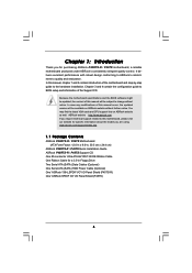
... for a 3.5-in Floppy Drive Two Serial ATA (SATA) Data Cables (Optional) One Serial ATA (SATA) HDD Power Cable (Optional) One "ASRock 1394_SPDIF I/O" I/O Panel Shield (P45TS-R) One "ASRock SPDIF I/O" I/O Panel Shield (P45TS) 5 Because the motherboard specifications and the BIOS software might be updated, the content of this manual will be subject to the hardware installation. In...
... for a 3.5-in Floppy Drive Two Serial ATA (SATA) Data Cables (Optional) One Serial ATA (SATA) HDD Power Cable (Optional) One "ASRock 1394_SPDIF I/O" I/O Panel Shield (P45TS-R) One "ASRock SPDIF I/O" I/O Panel Shield (P45TS) 5 Because the motherboard specifications and the BIOS software might be updated, the content of this manual will be subject to the hardware installation. In...
User Manual
Page 9
... / XP 64-bit / XP SP1 or SP2 / 2000 SP4. 11. ASRock website http://www.asrock.com 9 Some CPU you to SATAII mode. Please read "eSATAII Interface Introduction" on this motherboard supports both stereo and mono modes. CPU FSB Frequency Memory Support Frequency 1600 DDR2... installation procedures. 10. Please visit our website for proper installation. 5. This motherboard supports native FSB1600/1333/1066/800 MHz. For audio output, this motherboard supports 2-channel, 4- This motherboard supports eSATAII interface, the external SATAII specification. It allows you adopt may be...
... / XP 64-bit / XP SP1 or SP2 / 2000 SP4. 11. ASRock website http://www.asrock.com 9 Some CPU you to SATAII mode. Please read "eSATAII Interface Introduction" on this motherboard supports both stereo and mono modes. CPU FSB Frequency Memory Support Frequency 1600 DDR2... installation procedures. 10. Please visit our website for proper installation. 5. This motherboard supports native FSB1600/1333/1066/800 MHz. For audio output, this motherboard supports 2-channel, 4- This motherboard supports eSATAII interface, the external SATAII specification. It allows you adopt may be...

User Manual
Page 10
...It is recommended to page 58 for detailed setup. 1 . 3 Minimum Hardware Requirement Table for Windows® VistaTM Premium 2008 logo. 10 ASRock website: http://www.asrock.com 13. RAID / AHCI functions are required to meet above minimum hardware requirements in order to submit Windows® VistaTM Premium 2008 and ...the CPU. 14. 12. While CPU overheat is not recommended to get the best system performance under Windows® 2000. Although this motherboard and plan to qualify for Windows® VistaTM Premium 2008 and Basic Logo For system integrators and users who purchase this...
...It is recommended to page 58 for detailed setup. 1 . 3 Minimum Hardware Requirement Table for Windows® VistaTM Premium 2008 logo. 10 ASRock website: http://www.asrock.com 13. RAID / AHCI functions are required to meet above minimum hardware requirements in order to submit Windows® VistaTM Premium 2008 and ...the CPU. 14. 12. While CPU overheat is not recommended to get the best system performance under Windows® 2000. Although this motherboard and plan to qualify for Windows® VistaTM Premium 2008 and Basic Logo For system integrators and users who purchase this...
User Manual
Page 11
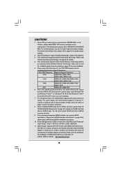
...240-pin DDR3 DIMM Slots (Dual Channel C: DDR3_A1, DDR3_B1; Yellow) 6 2 x 240-pin DDR2 DIMM Slots (Dual Channel B: DDRII_A2, DDRII_B2; 1.4 Motherboard Layout (P45TS-R) 12 3 4 24.4cm (9.6 in) PS2 Mouse PS2 Keyboard 40 1 PS2_USB_PWR1 56 7 Coaxial SPDIF Optical SPDIF 39 38 37 36 35 34 33 32...USB9 ATX12V1 USB 2.0 Top: T: USB2 IEEE B: USB3 1394 USB 2.0 T: USB0 Top: RJ-45 B: USB1 eSATAII_TOP CPU_FAN1 FSB1600 DDR2 1066 DDR3 1333 IDE1 P45TS-R Dual Channel Quad Core CPU ATXPWR1 Top: SIDE SPK Center: REAR SPK Bottom: CTR BASS Top: LINE IN Center: FRONT Bottom: MIC IN LAN PCIE1...
...240-pin DDR3 DIMM Slots (Dual Channel C: DDR3_A1, DDR3_B1; Yellow) 6 2 x 240-pin DDR2 DIMM Slots (Dual Channel B: DDRII_A2, DDRII_B2; 1.4 Motherboard Layout (P45TS-R) 12 3 4 24.4cm (9.6 in) PS2 Mouse PS2 Keyboard 40 1 PS2_USB_PWR1 56 7 Coaxial SPDIF Optical SPDIF 39 38 37 36 35 34 33 32...USB9 ATX12V1 USB 2.0 Top: T: USB2 IEEE B: USB3 1394 USB 2.0 T: USB0 Top: RJ-45 B: USB1 eSATAII_TOP CPU_FAN1 FSB1600 DDR2 1066 DDR3 1333 IDE1 P45TS-R Dual Channel Quad Core CPU ATXPWR1 Top: SIDE SPK Center: REAR SPK Bottom: CTR BASS Top: LINE IN Center: FRONT Bottom: MIC IN LAN PCIE1...

User Manual
Page 12
1.5 Motherboard Layout (P45TS) 12 3 24.4cm (9.6 in) 4 56 7 PS2 Mouse PS2 Keyboard 39 1 PS2_USB_PWR1 Coaxial SPDIF Optical SPDIF 38 37 36 35 34 33 32 31 30 29 ...-pin module) Bottom: USB 2.0 eSATAII T: USB8 B: USB9 ATX12V1 USB 2.0 T: USB2 B: USB3 USB 2.0 T: USB0 Top: RJ-45 B: USB1 eSATAII_TOP CPU_FAN1 FSB1600 DDR2 1066 DDR3 1333 IDE1 P45TS Dual Channel Quad Core CPU ATXPWR1 Top: SIDE SPK Center: REAR SPK Bottom: CTR BASS Top: LINE IN Center: FRONT Bottom: MIC IN LAN PCIE1...
1.5 Motherboard Layout (P45TS) 12 3 24.4cm (9.6 in) 4 56 7 PS2 Mouse PS2 Keyboard 39 1 PS2_USB_PWR1 Coaxial SPDIF Optical SPDIF 38 37 36 35 34 33 32 31 30 29 ...-pin module) Bottom: USB 2.0 eSATAII T: USB8 B: USB9 ATX12V1 USB 2.0 T: USB2 B: USB3 USB 2.0 T: USB0 Top: RJ-45 B: USB1 eSATAII_TOP CPU_FAN1 FSB1600 DDR2 1066 DDR3 1333 IDE1 P45TS Dual Channel Quad Core CPU ATXPWR1 Top: SIDE SPK Center: REAR SPK Bottom: CTR BASS Top: LINE IN Center: FRONT Bottom: MIC IN LAN PCIE1...

User Manual
Page 15
... edges and do so may cause severe damage to you install or remove any component. 2. Doing so may damage the motherboard. 2.2 Pre-installation Precautions Take note of your motherboard directly on a grounded antistatic pad or in the bag that the power is switched off or the power cord is an... ATX form factor (12.0" x 9.6", 30.5 x 24.4 cm) motherboard. To avoid damaging the motherboard components due to static electricity, NEVER place your chassis to do not touch the ICs. 4. Hold components by circles to secure the...
... edges and do so may cause severe damage to you install or remove any component. 2. Doing so may damage the motherboard. 2.2 Pre-installation Precautions Take note of your motherboard directly on a grounded antistatic pad or in the bag that the power is switched off or the power cord is an... ATX form factor (12.0" x 9.6", 30.5 x 24.4 cm) motherboard. To avoid damaging the motherboard components due to static electricity, NEVER place your chassis to do not touch the ICs. 4. Hold components by circles to secure the...

User Manual
Page 17
... CPU is recommended to use the cap tab to handle and avoid kicking off the PnP cap. 2. This cap must be placed if returning the motherboard for after service. Rotate the load plate onto the IHS. Secure load lever with the two alignment keys of the socket. Close the socket: Step...
... CPU is recommended to use the cap tab to handle and avoid kicking off the PnP cap. 2. This cap must be placed if returning the motherboard for after service. Rotate the load plate onto the IHS. Secure load lever with the two alignment keys of the socket. Close the socket: Step...

User Manual
Page 18
... caps with remaining fasteners. Step 4. Place the heatsink onto the socket. Step 6. Before you installed the heatsink, you press down on the motherboard (CPU_FAN1, see page 11/12, No. 2). Align fasteners with the CPU fan connector on side closest to the CPU_FAN connector (CPU_FAN1, see... adopt the type of heatsink and cooling fan compliant with 775-Pin socket that the CPU and the heatsink are oriented on the motherboard. Apply thermal interface material onto center of your CPU fan and heatsink. Rotate the fastener clockwise, then press down the fasteners without...
... caps with remaining fasteners. Step 4. Place the heatsink onto the socket. Step 6. Before you installed the heatsink, you press down on the motherboard (CPU_FAN1, see page 11/12, No. 2). Align fasteners with the CPU fan connector on side closest to the CPU_FAN connector (CPU_FAN1, see... adopt the type of heatsink and cooling fan compliant with 775-Pin socket that the CPU and the heatsink are oriented on the motherboard. Apply thermal interface material onto center of your CPU fan and heatsink. Rotate the fastener clockwise, then press down the fasteners without...

User Manual
Page 19
... set of green slots (DDR3_A1 and DDR3_B1), in the set of yellow slots (DDRII_A1 and DDRII_B1), or in the set of Memory Modules (DIMM) This motherboard provides four 240-pin DDR2 (Double Data Rate 2) DIMM slots and two 240-pin DDR3 (Double Data Rate 3) DIMM slots, and supports Dual Channel Memory... DIMM pair in all four slots. Yellow slots; see p.11/12 No.6), or identical DDR3 DIMM pair in the slots of the same color. This motherboard also allows you always need to install identical DDR2 DIMM pair in the slots of the same color. If you have to install identical (the...
... set of green slots (DDR3_A1 and DDR3_B1), in the set of yellow slots (DDRII_A1 and DDRII_B1), or in the set of Memory Modules (DIMM) This motherboard provides four 240-pin DDR2 (Double Data Rate 2) DIMM slots and two 240-pin DDR3 (Double Data Rate 3) DIMM slots, and supports Dual Channel Memory... DIMM pair in all four slots. Yellow slots; see p.11/12 No.6), or identical DDR3 DIMM pair in the slots of the same color. This motherboard also allows you always need to install identical DDR2 DIMM pair in the slots of the same color. If you have to install identical (the...

User Manual
Page 20
... or the system components. notch break notch break The DIMM only fits in one memory module is installed in the DDR2 DIMM slots on this motherboard, it is properly seated. 20 Firmly insert the DIMM into DDR3 slot; If a pair of memory modules is NOT installed in the same ... install a DDR2 memory module into the slot until the retaining clips at the same time. Step 1. Step 2. If only one correct orientation. otherwise, this motherboard at both ends fully snap back in DDRII_A1 and DDRII_B2, it is not allowed to activate the Dual Channel Memory Technology . 4. DDR2 and DDR3 memory...
... or the system components. notch break notch break The DIMM only fits in one memory module is installed in the DDR2 DIMM slots on this motherboard, it is properly seated. 20 Firmly insert the DIMM into DDR3 slot; If a pair of memory modules is NOT installed in the same ... install a DDR2 memory module into the slot until the retaining clips at the same time. Step 1. Step 2. If only one correct orientation. otherwise, this motherboard at both ends fully snap back in DDRII_A1 and DDRII_B2, it is not allowed to activate the Dual Channel Memory Technology . 4. DDR2 and DDR3 memory...

User Manual
Page 21
... bracket facing the slot that you start the installation. Align the card connector with x16 lane width graphics cards. White) is completely seated on this motherboard. White) is unplugged. Before installing the expansion card, please make necessary hardware settings for PCI Express cards with x1 lane width cards, such as Gigabit...
... bracket facing the slot that you start the installation. Align the card connector with x16 lane width graphics cards. White) is completely seated on this motherboard. White) is unplugged. Before installing the expansion card, please make necessary hardware settings for PCI Express cards with x1 lane width cards, such as Gigabit...

User Manual
Page 23
... connectors are NOT jumpers. Please refer to Pin1 Note: Make sure the red-striped side of the cable is plugged into Pin1 side of the motherboard! Please refer to below jumper settings. 4_5 FSB3 FSB2 3_4 FSB1 1_2 If you want to overclock the CPU you adopt to FSB1600 on this... refer to below jumper settings. 4_5 FSB3 FSB2 4_5 FSB1 1_2 If you want to overclock the CPU you adopt to FSB1333 on this motherboard. Do NOT place jumper caps over the headers and connectors will cause permanent damage of the connector. 23 If you want to overclock the CPU ...
... connectors are NOT jumpers. Please refer to Pin1 Note: Make sure the red-striped side of the cable is plugged into Pin1 side of the motherboard! Please refer to below jumper settings. 4_5 FSB3 FSB2 3_4 FSB1 1_2 If you want to overclock the CPU you adopt to FSB1600 on this... refer to below jumper settings. 4_5 FSB3 FSB2 4_5 FSB1 1_2 If you want to overclock the CPU you adopt to FSB1333 on this motherboard. Do NOT place jumper caps over the headers and connectors will cause permanent damage of the connector. 23 If you want to overclock the CPU ...

User Manual
Page 24
... eSATAII connector. 24 Primary IDE connector (Blue) (39-pin IDE1, see p.11/12 No. 8) PIN1 IDE1 connect the blue end to the motherboard connect the black end to the IDE devices 80-conductor ATA 66/100/133 cable Note: Please refer to the SATA / SATAII hard disk or... the SATAII connector on page 30 for external SATAII function. Please read "eSATAII Interface Introduction" on this motherboard. The current eSATAII interface allows up to 3.0 Gb/s data transfer rate. Serial ATAII Connectors (SATAII_1 (Port0): see p.11/12, No. 11) (SATAII_2 (...
... eSATAII connector. 24 Primary IDE connector (Blue) (39-pin IDE1, see p.11/12 No. 8) PIN1 IDE1 connect the blue end to the motherboard connect the black end to the IDE devices 80-conductor ATA 66/100/133 cable Note: Please refer to the SATA / SATAII hard disk or... the SATAII connector on page 30 for external SATAII function. Please read "eSATAII Interface Introduction" on this motherboard. The current eSATAII interface allows up to 3.0 Gb/s data transfer rate. Serial ATAII Connectors (SATAII_1 (Port0): see p.11/12, No. 11) (SATAII_2 (...
User Manual
Page 25
...+5V_2 TXN TXP GND2 PCIE_RST# +3SVB RX N RXP 1 GND1 D0-D0+ PexCLK PexCLK# USB+5V_1 PME# This header supports WiFi+AP function with ASRock WiFi-802.11g or WiFi-802.11n module, an easy-to support one USB 2.0 port. If you to create a wireless environment and enjoy the convenience...power cable to the power connector on each drive. Besides six default USB 2.0 ports on the I/O panel, there are two USB 2.0 headers on this motherboard, this picture for proper installation. Then connect the white end of SATA power cable to use wireless local area network (WLAN) adapter. Each USB 2.0...
...+5V_2 TXN TXP GND2 PCIE_RST# +3SVB RX N RXP 1 GND1 D0-D0+ PexCLK PexCLK# USB+5V_1 PME# This header supports WiFi+AP function with ASRock WiFi-802.11g or WiFi-802.11n module, an easy-to support one USB 2.0 port. If you to create a wireless environment and enjoy the convenience...power cable to the power connector on each drive. Besides six default USB 2.0 ports on the I/O panel, there are two USB 2.0 headers on this motherboard, this picture for proper installation. Then connect the white end of SATA power cable to use wireless local area network (WLAN) adapter. Each USB 2.0...

User Manual
Page 27
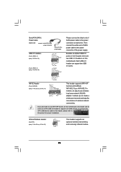
... functions. 1 SPEAKER DUMMY DUMMY +5V Please connect the chassis speaker to this connector. 24 12 Though this motherboard provides 24-pin ATX power connector, 13 1 it to the ground pin. Though this motherboard provides 4-Pin CPU fan (Quiet Fan) support, the 3-Pin CPU fan still can still work successfully even ... 27 CPU Fan Connector (4-pin CPU_FAN1) (see p.11, No. 38 or or p.12 No. 37) 13 1 Please connect an ATX power supply to this motherboard, please connect it can work if you plan to connect the 3-Pin CPU fan to the CPU fan connector on this header. If you adopt...
... functions. 1 SPEAKER DUMMY DUMMY +5V Please connect the chassis speaker to this connector. 24 12 Though this motherboard provides 24-pin ATX power connector, 13 1 it to the ground pin. Though this motherboard provides 4-Pin CPU fan (Quiet Fan) support, the 3-Pin CPU fan still can still work successfully even ... 27 CPU Fan Connector (4-pin CPU_FAN1) (see p.11, No. 38 or or p.12 No. 37) 13 1 Please connect an ATX power supply to this motherboard, please connect it can work if you plan to connect the 3-Pin CPU fan to the CPU fan connector on this header. If you adopt...

User Manual
Page 28
...system to the HDMI_SPDIF connector of HDMI_SPDIF cable to connect HDMI Digital TV/ projector/LCD devices. A. white end (2-pin) C. Though this motherboard. Please connect the black end (A) of HDMI VGA card to this connector. This IEEE 1394 header can still work if you adopt ...power supply. Please connect the HDMI_SPDIF connector of HDMI_SPDIF cable to the HDMI_SPDIF header on this motherboard provides 8-pin ATX 12V power connector, it can support one IEEE 1394 header (FRONT_1394) on the motherboard. ATX 12V Power Connector (8-pin ATX12V1) (see p.11 No. 30 or p.12 No...
...system to the HDMI_SPDIF connector of HDMI_SPDIF cable to connect HDMI Digital TV/ projector/LCD devices. A. white end (2-pin) C. Though this motherboard. Please connect the black end (A) of HDMI VGA card to this connector. This IEEE 1394 header can still work if you adopt ...power supply. Please connect the HDMI_SPDIF connector of HDMI_SPDIF cable to the HDMI_SPDIF header on this motherboard provides 8-pin ATX 12V power connector, it can support one IEEE 1394 header (FRONT_1394) on the motherboard. ATX 12V Power Connector (8-pin ATX12V1) (see p.11 No. 30 or p.12 No...

User Manual
Page 29
...manual of HDMI VGA card or other VGA card. Step 1. Step 2. Incorrect connection may be damaged. Step 5. For example, this motherboard and the HDMI VGA card. 2.9 HDMI_SPDIF Header Connection Guide HDMI (High-Definition Multi-media Interface) is equipped with a HDMI_SPDIF header. ...white end according to HDMI device, such as a digital television (DTV). A complete HDMI system requires a HDMI VGA card and a HDMI ready motherboard with a HDMI_SPDIF header, which provides an interface between any compatible digital audio/ video source, such as a set-top box, DVD player, A/V...
...manual of HDMI VGA card or other VGA card. Step 1. Step 2. Incorrect connection may be damaged. Step 5. For example, this motherboard and the HDMI VGA card. 2.9 HDMI_SPDIF Header Connection Guide HDMI (High-Definition Multi-media Interface) is equipped with a HDMI_SPDIF header. ...white end according to HDMI device, such as a digital television (DTV). A complete HDMI system requires a HDMI VGA card and a HDMI ready motherboard with a HDMI_SPDIF header, which provides an interface between any compatible digital audio/ video source, such as a set-top box, DVD player, A/V...
User Manual
Page 30
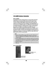
.... 3. 2.10 eSATAII Interface Introduction What is up to 400Mb/s. NOTE: 1. Currently, on and in working condition. 2. SATAII connector SATAII_6 (Port5) 30 eSATAII connector (eSATAII) This motherboard supports eSATAII interface, the external SATAII specification. If you still want to use eSATAII function in BIOS setup to the eSATAII ports only when the...
.... 3. 2.10 eSATAII Interface Introduction What is up to 400Mb/s. NOTE: 1. Currently, on and in working condition. 2. SATAII connector SATAII_6 (Port5) 30 eSATAII connector (eSATAII) This motherboard supports eSATAII interface, the external SATAII specification. If you still want to use eSATAII function in BIOS setup to the eSATAII ports only when the...

