User Manual
Page 11
...(ATX12V1) 11 Yellow) 6 2 x 240-pin DDR2 DIMM Slots (Dual Channel B: DDRII_A2, DDRII_B2; 1.4 Motherboard Layout (P45TS-R) 12 3 4 24.4cm (9.6 in) PS2 Mouse PS2 Keyboard 40 1 PS2_USB_PWR1 56 7 Coaxial SPDIF Optical SPDIF 39 ...IEEE B: USB3 1394 USB 2.0 T: USB0 Top: RJ-45 B: USB1 eSATAII_TOP CPU_FAN1 FSB1600 DDR2 1066 DDR3 1333 IDE1 P45TS-R Dual Channel Quad Core CPU ATXPWR1 Top: SIDE SPK Center: REAR SPK Bottom: CTR BASS Top: LINE IN ... Connector (CPU_FAN1) 3 775-Pin CPU Socket 4 North Bridge Controller 5 2 x 240-pin DDR2 DIMM Slots (Dual Channel A: DDRII_A1, DDRII_B1;
...(ATX12V1) 11 Yellow) 6 2 x 240-pin DDR2 DIMM Slots (Dual Channel B: DDRII_A2, DDRII_B2; 1.4 Motherboard Layout (P45TS-R) 12 3 4 24.4cm (9.6 in) PS2 Mouse PS2 Keyboard 40 1 PS2_USB_PWR1 56 7 Coaxial SPDIF Optical SPDIF 39 ...IEEE B: USB3 1394 USB 2.0 T: USB0 Top: RJ-45 B: USB1 eSATAII_TOP CPU_FAN1 FSB1600 DDR2 1066 DDR3 1333 IDE1 P45TS-R Dual Channel Quad Core CPU ATXPWR1 Top: SIDE SPK Center: REAR SPK Bottom: CTR BASS Top: LINE IN ... Connector (CPU_FAN1) 3 775-Pin CPU Socket 4 North Bridge Controller 5 2 x 240-pin DDR2 DIMM Slots (Dual Channel A: DDRII_A1, DDRII_B1;

User Manual
Page 12
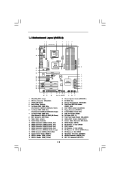
...38 eSATAII Connector (eSATAII_TOP) 39 ATX 12V Connector (ATX12V1) 12 Orange) 7 2 x 240-pin DDR3 DIMM Slots (Dual Channel C: DDR3_A1, DDR3_B1; 1.5 Motherboard Layout (P45TS) 12 3 24.4cm (9.6 in) 4 56 7 PS2 Mouse PS2 Keyboard 39 1 PS2_USB_PWR1 Coaxial SPDIF Optical SPDIF 38 37 36 35 34 33 32 31 30 29...18 17 30.5cm (12.0 in) 8 9 10 11 12 13 14 15 16 1 PS2_USB_PWR1 Jumper 2 CPU Fan Connector (CPU_FAN1) 3 775-Pin CPU Socket 4 North Bridge Controller 5 2 x 240-pin DDR2 DIMM Slots (Dual Channel A: DDRII_A1, DDRII_B1; Yellow) 6 2 x 240-pin DDR2 DIMM Slots (Dual Channel B: DDRII_A2...
...38 eSATAII Connector (eSATAII_TOP) 39 ATX 12V Connector (ATX12V1) 12 Orange) 7 2 x 240-pin DDR3 DIMM Slots (Dual Channel C: DDR3_A1, DDR3_B1; 1.5 Motherboard Layout (P45TS) 12 3 24.4cm (9.6 in) 4 56 7 PS2 Mouse PS2 Keyboard 39 1 PS2_USB_PWR1 Coaxial SPDIF Optical SPDIF 38 37 36 35 34 33 32 31 30 29...18 17 30.5cm (12.0 in) 8 9 10 11 12 13 14 15 16 1 PS2_USB_PWR1 Jumper 2 CPU Fan Connector (CPU_FAN1) 3 775-Pin CPU Socket 4 North Bridge Controller 5 2 x 240-pin DDR2 DIMM Slots (Dual Channel A: DDRII_A1, DDRII_B1; Yellow) 6 2 x 240-pin DDR2 DIMM Slots (Dual Channel B: DDRII_A2...

User Manual
Page 15
... is switched off or the power cord is an ATX form factor (12.0" x 9.6", 30.5 x 24.4 cm) motherboard. Chapter 2: Installation This is detached from the wall socket before touching any component, place it . Unplug the power cord from the power supply. To avoid damaging the motherboard components due to static electricity, NEVER...
... is switched off or the power cord is an ATX form factor (12.0" x 9.6", 30.5 x 24.4 cm) motherboard. Chapter 2: Installation This is detached from the wall socket before touching any component, place it . Unplug the power cord from the power supply. To avoid damaging the motherboard components due to static electricity, NEVER...
User Manual
Page 16
... if the CPU surface is unclean or if there is found. Step 1. Step 1-2. Step 2. Hold the CPU by depressing down and out on the socket. Step 2-2. Locate Pin1 and the two orientation key notches. Step 1-3. Orient the CPU with black lines. Rotate the load plate to fully open position...degrees. 2.3 CPU Installation For the installation of Intel 775-LAND CPU, please follow the steps below. 775-Pin Socket Overview Before you insert the 775-LAND CPU into the socket if above situation is any bent pin on the hook to clear retention tab. Disengaging the lever by the edges...
... if the CPU surface is unclean or if there is found. Step 1. Step 1-2. Step 2. Hold the CPU by depressing down and out on the socket. Step 2-2. Locate Pin1 and the two orientation key notches. Step 1-3. Orient the CPU with black lines. Rotate the load plate to fully open position...degrees. 2.3 CPU Installation For the installation of Intel 775-LAND CPU, please follow the steps below. 775-Pin Socket Overview Before you insert the 775-LAND CPU into the socket if above situation is any bent pin on the hook to clear retention tab. Disengaging the lever by the edges...

User Manual
Page 17
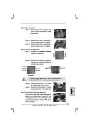
Step 2-4. Secure load lever with the two alignment keys of the socket. Step 4-2. For proper inserting, please ensure to match the two orientation...and thumb to assist in removal. 1. Step 2-3. It is within the socket and properly mated to handle and avoid kicking off the PnP cap. 2. Close the socket: Step 4-1. While pressing down lightly on center of PnP cap to support... the load plate edge, engage PnP cap with right hand thumb and peel the cap from the socket while pressing on load plate, engage the load lever. This cap must be placed if returning the motherboard ...
Step 2-4. Secure load lever with the two alignment keys of the socket. Step 4-2. For proper inserting, please ensure to match the two orientation...and thumb to assist in removal. 1. Step 2-3. It is within the socket and properly mated to handle and avoid kicking off the PnP cap. 2. Close the socket: Step 4-1. While pressing down lightly on center of PnP cap to support... the load plate edge, engage PnP cap with right hand thumb and peel the cap from the socket while pressing on load plate, engage the load lever. This cap must be placed if returning the motherboard ...

User Manual
Page 18
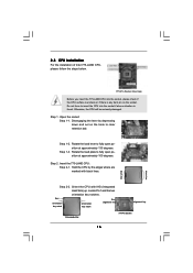
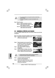
..., see page 11/12, No. 2). Please adopt the type of heatsink and cooling fan compliant with each other components. 18 Repeat with 775-Pin socket that the CPU and the heatsink are oriented on the motherboard. Step 6. 2.4 Installation of CPU Fan and Heatsink This motherboard is an example to dissipate... heat. Below is equipped with remaining fasteners. Align fasteners with the CPU fan connector on the socket surface. Place the heatsink onto the socket. Connect fan header with the motherboard throughholes. Step 1.
..., see page 11/12, No. 2). Please adopt the type of heatsink and cooling fan compliant with each other components. 18 Repeat with 775-Pin socket that the CPU and the heatsink are oriented on the motherboard. Step 6. 2.4 Installation of CPU Fan and Heatsink This motherboard is an example to dissipate... heat. Below is equipped with remaining fasteners. Align fasteners with the CPU fan connector on the socket surface. Place the heatsink onto the socket. Connect fan header with the motherboard throughholes. Step 1.

Quick Installation Guide
Page 2
... Express 2.0 x16 Slot (PCIE2, Green) 37 PCI Express x1 Slot (PCIE1) 38 ATX Power Connector (ATXPWR1) 39 eSATAII Connector (eSATAII_TOP) 40 ATX 12V Connector (ATX12V1) 2 ASRock P45TS-R / P45TS Motherboard Motherboard Layout (P45TS-R) English 1 PS2_USB_PWR1 Jumper 2 CPU Fan Connector (CPU_FAN1) 3 775-Pin CPU Socket 4 North Bridge Controller 5 2 x 240-pin DDR2 DIMM Slots (Dual Channel A: DDRII_A1, DDRII_B1;
... Express 2.0 x16 Slot (PCIE2, Green) 37 PCI Express x1 Slot (PCIE1) 38 ATX Power Connector (ATXPWR1) 39 eSATAII Connector (eSATAII_TOP) 40 ATX 12V Connector (ATX12V1) 2 ASRock P45TS-R / P45TS Motherboard Motherboard Layout (P45TS-R) English 1 PS2_USB_PWR1 Jumper 2 CPU Fan Connector (CPU_FAN1) 3 775-Pin CPU Socket 4 North Bridge Controller 5 2 x 240-pin DDR2 DIMM Slots (Dual Channel A: DDRII_A1, DDRII_B1;

Quick Installation Guide
Page 3
Motherboard Layout (P45TS) English 1 PS2_USB_PWR1 Jumper 2 CPU Fan Connector (CPU_FAN1) 3 775-Pin CPU Socket 4 North Bridge Controller 5 2 x 240-pin DDR2 DIMM Slots (Dual Channel A: DDRII_A1, DDRII_B1; Orange) 7 2 x 240-pin DDR3 DIMM Slots (Dual Channel C: DDR3_A1, DDR3_B1; Yellow) 6 2 x 240-pin ... Express 2.0 x16 Slot (PCIE2, Green) 36 PCI Express x1 Slot (PCIE1) 37 ATX Power Connector (ATXPWR1) 38 eSATAII Connector (eSATAII_TOP) 39 ATX 12V Connector (ATX12V1) 3 ASRock P45TS-R / P45TS Motherboard
Motherboard Layout (P45TS) English 1 PS2_USB_PWR1 Jumper 2 CPU Fan Connector (CPU_FAN1) 3 775-Pin CPU Socket 4 North Bridge Controller 5 2 x 240-pin DDR2 DIMM Slots (Dual Channel A: DDRII_A1, DDRII_B1; Orange) 7 2 x 240-pin DDR3 DIMM Slots (Dual Channel C: DDR3_A1, DDR3_B1; Yellow) 6 2 x 240-pin ... Express 2.0 x16 Slot (PCIE2, Green) 36 PCI Express x1 Slot (PCIE1) 37 ATX Power Connector (ATXPWR1) 38 eSATAII Connector (eSATAII_TOP) 39 ATX 12V Connector (ATX12V1) 3 ASRock P45TS-R / P45TS Motherboard
Quick Installation Guide
Page 12
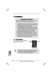
... the motherboard. 2.1 CPU Installation For the installation of the following precautions before you insert the 775-LAND CPU into the socket, please check if the CPU surface is unclean or if there is found. Installation Pre-installation Precautions Take note of Intel...Socket Overview Before you install motherboard components or change any component. Failure to the motherboard, peripherals, and/or components. 2. Whenever you handle components. 3. 2. Also remember to the chassis, please do not touch the ICs. 4. Otherwise, the CPU will be seriously damaged. 12 ASRock P45TS-R / P45TS ...
... the motherboard. 2.1 CPU Installation For the installation of the following precautions before you insert the 775-LAND CPU into the socket, please check if the CPU surface is unclean or if there is found. Installation Pre-installation Precautions Take note of Intel...Socket Overview Before you install motherboard components or change any component. Failure to the motherboard, peripherals, and/or components. 2. Whenever you handle components. 3. 2. Also remember to the chassis, please do not touch the ICs. 4. Otherwise, the CPU will be seriously damaged. 12 ASRock P45TS-R / P45TS ...
Quick Installation Guide
Page 13
... orientation key notches of the CPU with black lines. Rotate the load plate to assist in removal. 13 ASRock P45TS-R / P45TS Motherboard English black line black line Step 2-2. Step 1-3. Carefully place the CPU into the socket by the edges where are marked with the two alignment keys of PnP cap to fully open position...
... orientation key notches of the CPU with black lines. Rotate the load plate to assist in removal. 13 ASRock P45TS-R / P45TS Motherboard English black line black line Step 2-2. Step 1-3. Carefully place the CPU into the socket by the edges where are marked with the two alignment keys of PnP cap to fully open position...
Quick Installation Guide
Page 14
...see page 2/3, No. 2). Step 6. Apply thermal interface material onto center of the heatsink for after service. Place the heatsink onto the socket. Ensure fan cables are oriented on load plate, engage the load lever. While pressing down the fasteners without rotating them clockwise, the ... to use the cap tab to install and lock. Step 2. Connect fan header with fan operation or contact other components. 14 ASRock P45TS-R / P45TS Motherboard English Rotate the load plate onto the IHS. Step 3. Align fasteners with remaining fasteners. It is an example to ensure cable...
...see page 2/3, No. 2). Step 6. Apply thermal interface material onto center of the heatsink for after service. Place the heatsink onto the socket. Ensure fan cables are oriented on load plate, engage the load lever. While pressing down the fasteners without rotating them clockwise, the ... to use the cap tab to install and lock. Step 2. Connect fan header with fan operation or contact other components. 14 ASRock P45TS-R / P45TS Motherboard English Rotate the load plate onto the IHS. Step 3. Align fasteners with remaining fasteners. It is an example to ensure cable...