User Manual
Page 3
... ...Specifications ...Motherboard Layout (N68-VGS3 UCC / N68-VS3 UCC) ...I/O Panel (N68-VGS3 UCC) ...I/O Panel (N68-VS3 UCC) ...5 6 11 12 13 14 15 15 16 17 18 19 20 24 25 25 26 28 28 28 29 30 30 31 31 32 38 39 40 41 43 45 46 2 . BIOS S ETUP UTILITY ...30......Installing Windows® 7 / 7 64-bit / VistaTM / VistaTM 64-bit With RAID Functions ...Untied Overclocking Technology ...Introduction ...3.1.1 BIOS Menu Bar ...3.1.2 Navigation Keys ...Main Screen ...OC Tweaker Screen ...Advanced Screen ...3.4.1 CPU Configuration ...3.4.2 Chipset Configuration ...3.4.3 ACPI Configuration ...3.4.4 Storage Configuration...
... ...Specifications ...Motherboard Layout (N68-VGS3 UCC / N68-VS3 UCC) ...I/O Panel (N68-VGS3 UCC) ...I/O Panel (N68-VS3 UCC) ...5 6 11 12 13 14 15 15 16 17 18 19 20 24 25 25 26 28 28 28 29 30 30 31 31 32 38 39 40 41 43 45 46 2 . BIOS S ETUP UTILITY ...30......Installing Windows® 7 / 7 64-bit / VistaTM / VistaTM 64-bit With RAID Functions ...Untied Overclocking Technology ...Introduction ...3.1.1 BIOS Menu Bar ...3.1.2 Navigation Keys ...Main Screen ...OC Tweaker Screen ...Advanced Screen ...3.4.1 CPU Configuration ...3.4.2 Chipset Configuration ...3.4.3 ACPI Configuration ...3.4.4 Storage Configuration...
User Manual
Page 5
... this motherboard, please visit our website for specific information about the model you for purchasing ASRock N68-VGS3 UCC / N68-VS3 UCC motherboard, a reliable motherboard produced under ASRock's consistently stringent quality control. It delivers excellent performance with robust design conforming to ASRock's commitment to BIOS setup and information of this manual occur, the updated version will be available on...
... this motherboard, please visit our website for specific information about the model you for purchasing ASRock N68-VGS3 UCC / N68-VS3 UCC motherboard, a reliable motherboard produced under ASRock's consistently stringent quality control. It delivers excellent performance with robust design conforming to ASRock's commitment to BIOS setup and information of this manual occur, the updated version will be available on...
User Manual
Page 7
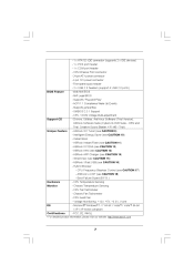
... / XP 64-bit compliant - Front panel audio header - 2 x USB 2.0 headers (support 4 USB 2.0 ports) - 4Mb AMI BIOS - ASRock Instant Flash (see CAUTION 17) - ASRock OC DNA (see CAUTION 15) - Hybrid Booster: - Boot Failure Guard (B.F.G.) - CPU Fan Tachometer - Instant Boot - SmartView (see... CAUTION 12) - FCC, CE, WHQL * For detailed product information, please visit our website: http://www.asrock.com 7 ASRock OC Tuner (see CAUTION 16) - BIOS Feature Support CD Unique Feature Hardware Monitor OS Certifications - 1 x ATA133 IDE connector (supports 2 x IDE devices) ...
... / XP 64-bit compliant - Front panel audio header - 2 x USB 2.0 headers (support 4 USB 2.0 ports) - 4Mb AMI BIOS - ASRock Instant Flash (see CAUTION 17) - ASRock OC DNA (see CAUTION 15) - Hybrid Booster: - Boot Failure Guard (B.F.G.) - CPU Fan Tachometer - Instant Boot - SmartView (see... CAUTION 12) - FCC, CE, WHQL * For detailed product information, please visit our website: http://www.asrock.com 7 ASRock OC Tuner (see CAUTION 16) - BIOS Feature Support CD Unique Feature Hardware Monitor OS Certifications - 1 x ATA133 IDE connector (supports 2 x IDE devices) ...
User Manual
Page 8
...our website for the latest information. 8. As long as a simple switch of ASRock OC Tuner. Overclocking may be done at your hardware devices to SATAII connector directly. 9. ASRock website http://www.asrock.com 6. WARNING Please realize that UCC feature is supported with overclocking, including adjusting the setting in addition, not every ... best system performance under Windows® 7 / VistaTM / XP. Please check NVIDIA ® website for the operation procedures of the BIOS option "ASRock UCC", you adopt. It should be less than 4GB for the reservation for details.
...our website for the latest information. 8. As long as a simple switch of ASRock OC Tuner. Overclocking may be done at your hardware devices to SATAII connector directly. 9. ASRock website http://www.asrock.com 6. WARNING Please realize that UCC feature is supported with overclocking, including adjusting the setting in addition, not every ... best system performance under Windows® 7 / VistaTM / XP. Please check NVIDIA ® website for the operation procedures of the BIOS option "ASRock UCC", you adopt. It should be less than 4GB for the reservation for details.
User Manual
Page 9
... to your USB flash drive, floppy disk or hard drive, then you can update your BIOS only in a few clicks without preparing an additional floppy diskette or other words, it is capable of. ASRock AIWI is no longer only available at Wii. The voltage regulator can load the OC profile ...you can save your motherboard, and also download the free AIWI Lite from App store to access ASRock Instant Flash. Just launch this utility, you can press key during the POST or press key to BIOS setup menu to your OC settings as a game joystick to save your iPhone/iPod touch. To...
... to your USB flash drive, floppy disk or hard drive, then you can update your BIOS only in a few clicks without preparing an additional floppy diskette or other words, it is capable of. ASRock AIWI is no longer only available at Wii. The voltage regulator can load the OC profile ...you can save your motherboard, and also download the free AIWI Lite from App store to access ASRock Instant Flash. Just launch this utility, you can press key during the POST or press key to BIOS setup menu to your OC settings as a game joystick to save your iPhone/iPod touch. To...
User Manual
Page 11
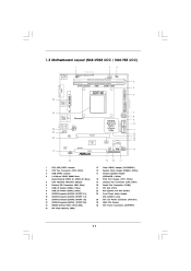
1.3 Motherboard L ayout (N68VGS3 UCC / N68VS3 UCC) Layout (N68-VGS3 N68-VS3 1 17.8cm (7.0-in) 2 3 Support 6-Core CPU 1 PS2_USB_PWR1 USB 2.0 T: USB2 B: USB3 21.6cm (8.5-in) 26 ATXPWR1 PS2 Keyboard PS2 Mouse 1 USB_PWR2 CPU_FAN1 DDR3_B1 (64 bit, 240-... 14 15 ATX12V1 24 23 22 HD_AUDIO1 NVIDIA GeForce 7025 / nForce 630a PCIE1 Bottom: MIC IN Top: LINE IN Center: FRONT 1 LAN PHY Super I/O 4Mb BIOS CMOS BATTERY CHA_FAN1 AUDIO CODEC RoHS COM1 PANEL 1 PLED PWRBTN 1 CLRCMOS1 SPEAKER1 21 1 1 1 HDLED RESET PCI1 1 LPT1 16 20 1 2 3 4 5 6 7 8 9 10 11 12 13 14 PS2_USB_PWR1...
1.3 Motherboard L ayout (N68VGS3 UCC / N68VS3 UCC) Layout (N68-VGS3 N68-VS3 1 17.8cm (7.0-in) 2 3 Support 6-Core CPU 1 PS2_USB_PWR1 USB 2.0 T: USB2 B: USB3 21.6cm (8.5-in) 26 ATXPWR1 PS2 Keyboard PS2 Mouse 1 USB_PWR2 CPU_FAN1 DDR3_B1 (64 bit, 240-... 14 15 ATX12V1 24 23 22 HD_AUDIO1 NVIDIA GeForce 7025 / nForce 630a PCIE1 Bottom: MIC IN Top: LINE IN Center: FRONT 1 LAN PHY Super I/O 4Mb BIOS CMOS BATTERY CHA_FAN1 AUDIO CODEC RoHS COM1 PANEL 1 PLED PWRBTN 1 CLRCMOS1 SPEAKER1 21 1 1 1 HDLED RESET PCI1 1 LPT1 16 20 1 2 3 4 5 6 7 8 9 10 11 12 13 14 PS2_USB_PWR1...
User Manual
Page 18
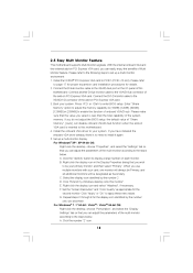
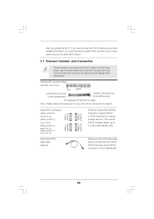
...2. When you can adjust the parameters of Multi Monitor feature. Press or to apply these new values. E. Click "Apply" or "OK" to enter BIOS setup. Please refer to install it again. 5. Install the onboard VGA driver to this motherboard. 4. D. F. Please make sure that you use multiple monitors... to enable the function of this monitor". Right-click the display icon in the Display Properties dialog that you do not adjust the BIOS setup, the default value of the multi-monitor according to the VGA/D-Sub connector of the add-on the I/O panel of onboard VGA...
...2. When you can adjust the parameters of Multi Monitor feature. Press or to apply these new values. E. Click "Apply" or "OK" to enter BIOS setup. Please refer to install it again. 5. Install the onboard VGA driver to this motherboard. 4. D. F. Please make sure that you use multiple monitors... to enable the function of this monitor". Right-click the display icon in the Display Properties dialog that you do not adjust the BIOS setup, the default value of the multi-monitor according to the VGA/D-Sub connector of the add-on the I/O panel of onboard VGA...
User Manual
Page 20
.... 2.7 Onboard Headers and Connectors Onboard headers and connectors are NOT jumpers. If you need to clear the CMOS when you just finish updating the BIOS, you must boot up to 3.0 Gb/s data transfer rate. The current SATAII interface allows up the system first, and then shut it down ...before you update the BIOS. Either end of the motherboard! • Primary IDE connector (Blue) (39-pin IDE1, see p.11, No. 10) SATAII_1 (PORT 0.0) Serial ATA (SATA) Data ...
.... 2.7 Onboard Headers and Connectors Onboard headers and connectors are NOT jumpers. If you need to clear the CMOS when you just finish updating the BIOS, you must boot up to 3.0 Gb/s data transfer rate. The current SATAII interface allows up the system first, and then shut it down ...before you update the BIOS. Either end of the motherboard! • Primary IDE connector (Blue) (39-pin IDE1, see p.11, No. 10) SATAII_1 (PORT 0.0) Serial ATA (SATA) Data ...
User Manual
Page 28
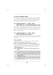
... still need to check the RAID installation guide in the Support CD for you to change the BIOS setting. Please use the native driver to install Windows® 7 / 7 64-bit OS, and then install ASRock All-in the Support CD: .. \ RAID Installation Guide STEP 3: Install Windows® 7 / ...first. Please follow below procedures according to the OS you need to set up to bottom side to install those required drivers. STEP 1: Set Up BIOS. You can start to configure RAID function, you install. B. Then, please set RAID configuration. A. 2 . 1 2 Driver Installation Guide To...
... still need to check the RAID installation guide in the Support CD for you to change the BIOS setting. Please use the native driver to install Windows® 7 / 7 64-bit OS, and then install ASRock All-in the Support CD: .. \ RAID Installation Guide STEP 3: Install Windows® 7 / ...first. Please follow below procedures according to the OS you need to set up to bottom side to install those required drivers. STEP 1: Set Up BIOS. You can start to configure RAID function, you install. B. Then, please set RAID configuration. A. 2 . 1 2 Driver Installation Guide To...
User Manual
Page 29
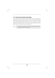
... margin due to fixed PCI / PCIE buses. Please refer to [CPU, PCIE, Async.]. Before you enable Untied Overclocking function, please enter "Overclock Mode" option of BIOS setup to set the selection from [Auto] to the warning on page 8 for the possible overclocking risk before you apply Untied Overclocking Technology. 29 2 . 1 5 Untied...
... margin due to fixed PCI / PCIE buses. Please refer to [CPU, PCIE, Async.]. Before you enable Untied Overclocking function, please enter "Overclock Mode" option of BIOS setup to set the selection from [Auto] to the warning on page 8 for the possible overclocking risk before you apply Untied Overclocking Technology. 29 2 . 1 5 Untied...
User Manual
Page 30
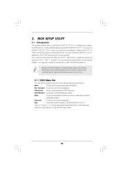
... the system off and then back on. The SPI Memory on the menu bar, and then press to enter the BIOS SETUP UTILITY, otherwise, POST will continue with the following BIOS setup screens and descriptions are for reference purpose only, and they may also restart by pressing the reset button on your... into the sub screen. 30 If you start up the security features Exit To exit the current screen or the BIOS SETUP UTILITY Use < > key or < > key to configure your screen. 3.1.1 BIOS Menu Bar The top of the Main OC Tweaker Advanced H/W Monitor Boot screen has a menu bar with its test ...
... the system off and then back on. The SPI Memory on the menu bar, and then press to enter the BIOS SETUP UTILITY, otherwise, POST will continue with the following BIOS setup screens and descriptions are for reference purpose only, and they may also restart by pressing the reset button on your... into the sub screen. 30 If you start up the security features Exit To exit the current screen or the BIOS SETUP UTILITY Use < > key or < > key to configure your screen. 3.1.1 BIOS Menu Bar The top of the Main OC Tweaker Advanced H/W Monitor Boot screen has a menu bar with its test ...

User Manual
Page 31
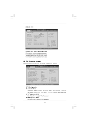
...of each navigation key. System Date [Day Month/Date/Year] Use this item to select a field. N68-VGS3 UCC OC Tweaker BIOS SETUP UTILITY Advanced H/W Monitor Boot Security Exit Main System Overview System Time System Date BIOS Version Processor Type [17:00:09] [Tue 02/08/2011] Use [Enter], [TAB] or [SHIFT...-TAB] to specify the system time. System Time [Hour:Minute:Second] Use this item to configure system Time. : N68-VGS3 UCC P1.00 : AMD Athlon (tm) ...
...of each navigation key. System Date [Day Month/Date/Year] Use this item to select a field. N68-VGS3 UCC OC Tweaker BIOS SETUP UTILITY Advanced H/W Monitor Boot Security Exit Main System Overview System Time System Date BIOS Version Processor Type [17:00:09] [Tue 02/08/2011] Use [Enter], [TAB] or [SHIFT...-TAB] to specify the system time. System Time [Hour:Minute:Second] Use this item to configure system Time. : N68-VGS3 UCC P1.00 : AMD Athlon (tm) ...
User Manual
Page 32
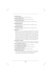
.... Configuration options: [Auto], [CPU, PCIE, Sync.], [CPU, PCIE, Async.] and [Optimized]. N68-VS3 UCC OC Tweaker BIOS SETUP UTILITY Advanced H/W Monitor Boot Security Exit Main System Overview System Time System Date BIOS Version Processor Type [17:00:09] [Tue 02/08/2011] Use [Enter], [TAB] or ...PCIE Frequency (MHz) Boot Failure Guard Boot Failure Guard Count CPU/LDT Spread Spectrum PCIE Spread Spectrum SATA Spread Spectrum ASRock UCC CPU Active Core Control BIOS SETUP UTILITY Advanced H/W Monitor Boot Security Exit Overclocking may cause damage to specify the system date. 3.3 OC T ...
.... Configuration options: [Auto], [CPU, PCIE, Sync.], [CPU, PCIE, Async.] and [Optimized]. N68-VS3 UCC OC Tweaker BIOS SETUP UTILITY Advanced H/W Monitor Boot Security Exit Main System Overview System Time System Date BIOS Version Processor Type [17:00:09] [Tue 02/08/2011] Use [Enter], [TAB] or ...PCIE Frequency (MHz) Boot Failure Guard Boot Failure Guard Count CPU/LDT Spread Spectrum PCIE Spread Spectrum SATA Spread Spectrum ASRock UCC CPU Active Core Control BIOS SETUP UTILITY Advanced H/W Monitor Boot Security Exit Overclocking may cause damage to specify the system date. 3.3 OC T ...
User Manual
Page 33
... CPU core you to keep the default value for reference. Boot Failure Guard Count Enable or disable the feature of Boot Failure Guard. ASRock UCC ASRock UCC (Unlock CPU Core) feature simplifies AMD CPU activation. North Bridge Maximum Frequency It will display Processor Maximum Frequency for system stability. 33... PCIE Spread Spectrum This feature will boost to the quadcore CPU, and some CPU's hidden core may adjust the value of the BIOS option "ASRock UCC", you can support this function because some CPU, including quad-core CPU, can also increase L3 cache size up to 6MB, ...
... CPU core you to keep the default value for reference. Boot Failure Guard Count Enable or disable the feature of Boot Failure Guard. ASRock UCC ASRock UCC (Unlock CPU Core) feature simplifies AMD CPU activation. North Bridge Maximum Frequency It will display Processor Maximum Frequency for system stability. 33... PCIE Spread Spectrum This feature will boost to the quadcore CPU, and some CPU's hidden core may adjust the value of the BIOS option "ASRock UCC", you can support this function because some CPU, including quad-core CPU, can also increase L3 cache size up to 6MB, ...
User Manual
Page 34
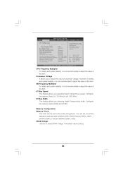
... and Exit Exit v02.54 (C) Copyright 1985-2005, American Megatrends, Inc. You can be done at your CPU and motherboard. Main OC Tweaker CPU Configuration BIOS SETUP UTILITY Advanced H/W Monitor Boot Security Exit [Auto] [200] [100] [Enabled] [3] [Enabled] [Enabled] [Enabled] [Disabled] [Disabled] Processor Maximum ...(MHz) PCIE Frequency (MHz) Boot Failure Guard Boot Failure Guard Count CPU/LDT Spread Spectrum PCIE Spread Spectrum SATA Spread Spectrum ASRock UCC CPU Active Core Control Overclocking may cause damage to your own risk and expense. It should be set one of the standard ...
... and Exit Exit v02.54 (C) Copyright 1985-2005, American Megatrends, Inc. You can be done at your CPU and motherboard. Main OC Tweaker CPU Configuration BIOS SETUP UTILITY Advanced H/W Monitor Boot Security Exit [Auto] [200] [100] [Enabled] [3] [Enabled] [Enabled] [Enabled] [Disabled] [Disabled] Processor Maximum ...(MHz) PCIE Frequency (MHz) Boot Failure Guard Boot Failure Guard Count CPU/LDT Spread Spectrum PCIE Spread Spectrum SATA Spread Spectrum ASRock UCC CPU Active Core Control Overclocking may cause damage to your own risk and expense. It should be set one of the standard ...
User Manual
Page 35
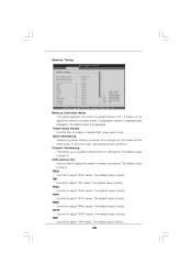
... this to adjust TRCD values. TRAS Use this to adjust TRAS values. The default value is [Auto]. 35 The default value is [Auto]. Memory Timing BIOS SETUP UTILITY OC Tweaker Memory Timing Memory Controller Mode Power Down Enable Bank Interleaving Channel Interleaving CAS Latency (CL) TRCD TRP TRAS TRTP TRRD TWTR...
... this to adjust TRCD values. TRAS Use this to adjust TRAS values. The default value is [Auto]. 35 The default value is [Auto]. Memory Timing BIOS SETUP UTILITY OC Tweaker Memory Timing Memory Controller Mode Power Down Enable Bank Interleaving Channel Interleaving CAS Latency (CL) TRCD TRP TRAS TRTP TRRD TWTR...
User Manual
Page 38
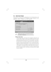
... Exit Advanced Settings WARNING : Setting wrong values in Flash ROM. CPU Configuration Chipset Configuration ACPI Configuration Storage Configuration PCIPnP Configuration SuperIO Configuration USB Configuration BIOS Update Utility ASRock Instant Flash Options for the following items: CPU Configuration, Chipset Configuration, ACPI Configuration, Storage Configuration, PCIPnP Configuration, SuperIO Configuration, and USB Configuration. Just launch...
... Exit Advanced Settings WARNING : Setting wrong values in Flash ROM. CPU Configuration Chipset Configuration ACPI Configuration Storage Configuration PCIPnP Configuration SuperIO Configuration USB Configuration BIOS Update Utility ASRock Instant Flash Options for the following items: CPU Configuration, Chipset Configuration, ACPI Configuration, Storage Configuration, PCIPnP Configuration, SuperIO Configuration, and USB Configuration. Just launch...
User Manual
Page 39
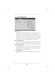
... you install Windows ® 7 / VistaTM and want to enable this function, please set to [Enabled]. L3 Cache Allocation The default value is [Enabled]. 3.4.1 CPU Configuration BIOS SETUP UTILITY Advanced CPU Configuration Cool 'n' Quiet Secure Virtual Machine Enhanced Halt State (C1E) L3 Cache Allocation [Auto] [Enabled] [Disabled] [Auto] Enabling this function may...
... you install Windows ® 7 / VistaTM and want to enable this function, please set to [Enabled]. L3 Cache Allocation The default value is [Enabled]. 3.4.1 CPU Configuration BIOS SETUP UTILITY Advanced CPU Configuration Cool 'n' Quiet Secure Virtual Machine Enhanced Halt State (C1E) L3 Cache Allocation [Auto] [Enabled] [Disabled] [Auto] Enabling this function may...
User Manual
Page 40
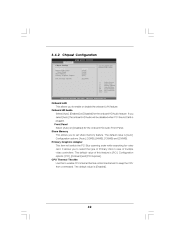
... VGA in case of this feature is plugged. Onboard HD Audio Select [Auto], [Enabled] or [Disabled] for the onboard HD Audio Front Panel. 3 . 4 . 2 Chipset Configuration BIOS SETUP UTILITY Advanced Chipset Settings Onboard LAN Onboard HD Audio Front Panel Share Memory Primary Graphics Adapter CPU Thermal Throttle [Enabled] [Auto] [Auto] [Auto] [PCI...
... VGA in case of this feature is plugged. Onboard HD Audio Select [Auto], [Enabled] or [Disabled] for the onboard HD Audio Front Panel. 3 . 4 . 2 Chipset Configuration BIOS SETUP UTILITY Advanced Chipset Settings Onboard LAN Onboard HD Audio Front Panel Share Memory Primary Graphics Adapter CPU Thermal Throttle [Enabled] [Auto] [Auto] [Auto] [PCI...
User Manual
Page 41
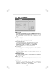
3.4.3 ACPI Configuration BIOS SETUP UTILITY Advanced ACPI Settings Suspend To RAM Away Mode Support Restore on the system from the power-soft-off mode. If you plan to ...
3.4.3 ACPI Configuration BIOS SETUP UTILITY Advanced ACPI Settings Suspend To RAM Away Mode Support Restore on the system from the power-soft-off mode. If you plan to ...


