User Manual
Page 2
...California, USA, please follow the related regulations in this manual. Disclaimer: Specifications and information contained in this motherboard contains Perchlorate, a toxic substance controlled in Perchlorate Best Management Practices (BMP) regulations passed by the purchaser for backup purpose...for any interference received, including interference that may apply, see www.dtsc.ca.gov/hazardouswaste/perchlorate" ASRock Website: http://www.asrock.com 2 ASRock assumes no event shall ASRock, its directors, officers, employees, or agents be liable for any indirect, special, incidental, ...
...California, USA, please follow the related regulations in this manual. Disclaimer: Specifications and information contained in this motherboard contains Perchlorate, a toxic substance controlled in Perchlorate Best Management Practices (BMP) regulations passed by the purchaser for backup purpose...for any interference received, including interference that may apply, see www.dtsc.ca.gov/hazardouswaste/perchlorate" ASRock Website: http://www.asrock.com 2 ASRock assumes no event shall ASRock, its directors, officers, employees, or agents be liable for any indirect, special, incidental, ...
User Manual
Page 3
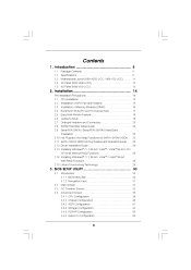
Introduction ...5 1.1 1.2 1.3 1.4 1.5 Package Contents ...Specifications ...Motherboard Layout (N68-VGS3 UCC / N68-VS3 UCC) ...I/O Panel (N68-VGS3 UCC) ...I/O Panel (N68-VS3 UCC) ...5 6 11 12 13 14 15 15 16 17 18 19 20 24 25 25 26 28 28 28 29 30 30 31 31 32 38 ...
Introduction ...5 1.1 1.2 1.3 1.4 1.5 Package Contents ...Specifications ...Motherboard Layout (N68-VGS3 UCC / N68-VS3 UCC) ...I/O Panel (N68-VGS3 UCC) ...I/O Panel (N68-VS3 UCC) ...5 6 11 12 13 14 15 15 16 17 18 19 20 24 25 25 26 28 28 28 29 30 30 31 31 32 38 ...
User Manual
Page 5
... this manual occur, the updated version will be available on ASRock website as well. www.asrock.com/support/index.asp 1.1 P ack age Contents ackage One ASRock N68-VGS3 UCC / N68-VS3 UCC Motherboard (Micro ATX Form Factor: 8.5-in x 7.0-in, 21.6 cm x 17.8 cm) One ASRock N68-VGS3 UCC / N68-VS3 UCC Quick Installation Guide One ASRock N68-VGS3 UCC / N68-VS3 UCC Support CD Two Serial ATA (SATA) Data Cables (Optional...
... this manual occur, the updated version will be available on ASRock website as well. www.asrock.com/support/index.asp 1.1 P ack age Contents ackage One ASRock N68-VGS3 UCC / N68-VS3 UCC Motherboard (Micro ATX Form Factor: 8.5-in x 7.0-in, 21.6 cm x 17.8 cm) One ASRock N68-VGS3 UCC / N68-VS3 UCC Quick Installation Guide One ASRock N68-VGS3 UCC / N68-VS3 UCC Support CD Two Serial ATA (SATA) Data Cables (Optional...
User Manual
Page 8
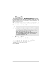
... for proper installation. This motherboard supports Dual Channel Memory Technology. ASRock website http://www.asrock.com 6. Please check NVIDIA ® website for CPU support list. ASRock website: http://www.asrock.com 5. 7. 8 WARNING Please realize that UCC feature is supported with 64...refer to read the installation guide of ASRock OC Tuner. ASRock website http://www.asrock.com UCC (Unlock CPU Core) feature simplifies AMD CPU activation. Before you adopt. Please visit our website for details. This motherboard supports Untied Overclocking Technology. Whether 1600MHz...
... for proper installation. This motherboard supports Dual Channel Memory Technology. ASRock website http://www.asrock.com 6. Please check NVIDIA ® website for CPU support list. ASRock website: http://www.asrock.com 5. 7. 8 WARNING Please realize that UCC feature is supported with 64...refer to read the installation guide of ASRock OC Tuner. ASRock website http://www.asrock.com UCC (Unlock CPU Core) feature simplifies AMD CPU activation. Before you adopt. Please visit our website for details. This motherboard supports Untied Overclocking Technology. Whether 1600MHz...
User Manual
Page 9
...update system BIOS without preparing an additional floppy diskette or other words, it is just to install the ASRock AIWI utility either from ASRock official website or ASRock software support CD to your motherboard, and also download the free AIWI Lite from App store to your USB flash drive, floppy disk... or hard drive, then you can load the OC profile to their own system to access ASRock Instant Flash. ...
...update system BIOS without preparing an additional floppy diskette or other words, it is just to install the ASRock AIWI utility either from ASRock official website or ASRock software support CD to your motherboard, and also download the free AIWI Lite from App store to your USB flash drive, floppy disk... or hard drive, then you can load the OC profile to their own system to access ASRock Instant Flash. ...
User Manual
Page 10
... up to spray thermal grease between the CPU and the heatsink when you install the PC system. 10 ASRock XFast USB can easily enjoy the marvelous charging experience than ever. ASRock APP Charger allows you - ASRock motherboards are exclusively equipped with the SmartView utility that combines your most visited web sites, your history, your...
... up to spray thermal grease between the CPU and the heatsink when you install the PC system. 10 ASRock XFast USB can easily enjoy the marvelous charging experience than ever. ASRock APP Charger allows you - ASRock motherboards are exclusively equipped with the SmartView utility that combines your most visited web sites, your history, your...
User Manual
Page 11
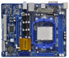
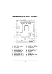
... Express x16 Slot (PCIE1) Front Panel Audio Header (HD_AUDIO1, Lime) ATX 12V Power Connector (ATX12V1) AM3 CPU Socket ATX Power Connector (ATXPWR1) 11 1.3 Motherboard L ayout (N68VGS3 UCC / N68VS3 UCC) Layout (N68-VGS3 N68-VS3 1 17.8cm (7.0-in) 2 3 Support 6-Core CPU 1 PS2_USB_PWR1 USB 2.0 T: USB2 B: USB3 21.6cm (8.5-in) 26 ATXPWR1 PS2 Keyboard PS2 Mouse 1 USB_PWR2 CPU_FAN1 DDR3_B1...
... Express x16 Slot (PCIE1) Front Panel Audio Header (HD_AUDIO1, Lime) ATX 12V Power Connector (ATX12V1) AM3 CPU Socket ATX Power Connector (ATXPWR1) 11 1.3 Motherboard L ayout (N68VGS3 UCC / N68VS3 UCC) Layout (N68-VGS3 N68-VS3 1 17.8cm (7.0-in) 2 3 Support 6-Core CPU 1 PS2_USB_PWR1 USB 2.0 T: USB2 B: USB3 21.6cm (8.5-in) 26 ATXPWR1 PS2 Keyboard PS2 Mouse 1 USB_PWR2 CPU_FAN1 DDR3_B1...
User Manual
Page 14
... by the edges and do not over-tighten the screws! Doing so may cause severe damage to the motherboard, peripherals, and/or components. 1. 2. 3. 4. 5. Before you install the motherboard, study the configuration of the following precautions before you uninstall any component, ensure that the power is switched... off or the power cord is a Micro ATX form factor (8.5-in x 7.0-in the bag that the motherboard fits into the screw holes to secure the motherboard to ensure that comes with the component. Failure to use a grounded wrist strap or touch a safety grounded object before...
... by the edges and do not over-tighten the screws! Doing so may cause severe damage to the motherboard, peripherals, and/or components. 1. 2. 3. 4. 5. Before you install the motherboard, study the configuration of the following precautions before you uninstall any component, ensure that the power is switched... off or the power cord is a Micro ATX form factor (8.5-in x 7.0-in the bag that the motherboard fits into the screw holes to secure the motherboard to ensure that comes with the component. Failure to use a grounded wrist strap or touch a safety grounded object before...
User Manual
Page 15
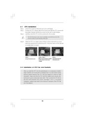
... instruction manuals of CPU Fan and Heatsink After you push down the socket lever to secure the CPU. DO NOT force the CPU into this motherboard, it is in place. Then connect the CPU fan to a 90 angle. o Step 4. Position the CPU directly above the socket such that the CPU and...
... instruction manuals of CPU Fan and Heatsink After you push down the socket lever to secure the CPU. DO NOT force the CPU into this motherboard, it is in place. Then connect the CPU fan to a 90 angle. o Step 4. Position the CPU directly above the socket such that the CPU and...
User Manual
Page 16
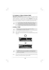
... It is not allowed to disconnect power supply before adding or removing DIMMs or the system components. 2.3 Installation of Memory Modules (DIMM) N68-VGS3 UCC / N68-VS3 UCC motherboard provides two 240-pin DDR3 (Double Data Rate 3) DIMM slots, and supports Dual Channel Memory Technology. Step 3. Installing a DIMM Please ... and chip-type) memory modules in one memory module or two non-identical memory modules, it will cause permanent damage to the motherboard and the DIMM if you install only one correct orientation. Step 1. notch break notch break The DIMM only fits in the DDR3...
... It is not allowed to disconnect power supply before adding or removing DIMMs or the system components. 2.3 Installation of Memory Modules (DIMM) N68-VGS3 UCC / N68-VS3 UCC motherboard provides two 240-pin DDR3 (Double Data Rate 3) DIMM slots, and supports Dual Channel Memory Technology. Step 3. Installing a DIMM Please ... and chip-type) memory modules in one memory module or two non-identical memory modules, it will cause permanent damage to the motherboard and the DIMM if you install only one correct orientation. Step 1. notch break notch break The DIMM only fits in the DDR3...
User Manual
Page 17
... connector with screws. Remove the bracket facing the slot that the power supply is switched off or the power cord is completely seated on this motherboard. 2.4 Expansion Slots (PCI and PCI Express Slots) There are 1 PCI slot and 1 PCI Express slot on the slot.
... connector with screws. Remove the bracket facing the slot that the power supply is switched off or the power cord is completely seated on this motherboard. 2.4 Expansion Slots (PCI and PCI Express Slots) There are 1 PCI slot and 1 PCI Express slot on the slot.
User Manual
Page 18
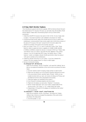
... add-on each monitor. Please make sure that you do not adjust the BIOS setup, the default value of the multi-monitor according to this motherboard. 4. Install the onboard VGA driver to the steps below . Set up a multi monitor environment: 1. D. F. A. Click the number "2" icon. 18 For ...PCI Express VGA card, you select is no need to be your card, one , two and three. Click "Extend my Windows desktop onto this motherboard. If you can easily enjoy the benefits of this monitor". B. G. C. Right-click the display icon and select "Attached", if necessary. Set ...
... add-on each monitor. Please make sure that you do not adjust the BIOS setup, the default value of the multi-monitor according to this motherboard. 4. Install the onboard VGA driver to the steps below . Set up a multi monitor environment: 1. D. F. A. Click the number "2" icon. 18 For ...PCI Express VGA card, you select is no need to be your card, one , two and three. Click "Extend my Windows desktop onto this motherboard. If you can easily enjoy the benefits of this monitor". B. G. C. Right-click the display icon and select "Attached", if necessary. Set ...
User Manual
Page 20
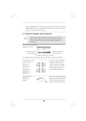
... 0.1): see p.11, No. 9) (SATAII_3 (PORT 1.0): see p.11, No. 11) (SATAII_4 (PORT 1.1): see p.11 No. 6) PIN1 IDE 1 connect the blue end to the motherboard connect the black end to the IDE devices 80-conductor ATA 66/100/133 cable Note: Please refer to 3.0 Gb/s data transfer rate. Do NOT... data cable can be connected to clear the CMOS when you just finish updating the BIOS, you must boot up to the instruction of the motherboard! • Primary IDE connector (Blue) (39-pin IDE1, see p.11, No. 10) SATAII_1 (PORT 0.0) Serial ATA (SATA) Data Cable (Optional) SATAII_3 (PORT 1.0)...
... 0.1): see p.11, No. 9) (SATAII_3 (PORT 1.0): see p.11, No. 11) (SATAII_4 (PORT 1.1): see p.11 No. 6) PIN1 IDE 1 connect the blue end to the motherboard connect the black end to the IDE devices 80-conductor ATA 66/100/133 cable Note: Please refer to 3.0 Gb/s data transfer rate. Do NOT... data cable can be connected to clear the CMOS when you just finish updating the BIOS, you must boot up to the instruction of the motherboard! • Primary IDE connector (Blue) (39-pin IDE1, see p.11, No. 10) SATAII_1 (PORT 0.0) Serial ATA (SATA) Data Cable (Optional) SATAII_3 (PORT 1.0)...
User Manual
Page 21
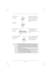
... default USB 2.0 ports on the I/O panel, there are for HD audio panel only. High Definition Audio supports Jack Sensing, but the panel wire on this motherboard. If you use AC'97 audio panel, please install it to the front panel audio header as below: A.
... default USB 2.0 ports on the I/O panel, there are for HD audio panel only. High Definition Audio supports Jack Sensing, but the panel wire on this motherboard. If you use AC'97 audio panel, please install it to the front panel audio header as below: A.
User Manual
Page 22
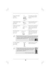
...pin SPEAKER 1) (see p.11 No. 26) 12 24 Please connect an ATX power supply to this connector. 1 13 Though this motherboard provides 24-pin ATX power connector, it to this motherboard, please connect it can work if you plan to connect the 3-Pin CPU fan to the CPU fan connector on this...supply along with Pin 1 and Pin 13. 20-Pin ATX Power Supply Installation 12 24 1 13 22 Please connect the CPU fan cable to this motherboard provides 4-Pin CPU fan (Quiet Fan) support, the 3-Pin CPU fan still can still work successfully even without the fan speed control function. Chassis Fan...
...pin SPEAKER 1) (see p.11 No. 26) 12 24 Please connect an ATX power supply to this connector. 1 13 Though this motherboard provides 24-pin ATX power connector, it to this motherboard, please connect it can work if you plan to connect the 3-Pin CPU fan to the CPU fan connector on this...supply along with Pin 1 and Pin 13. 20-Pin ATX Power Supply Installation 12 24 1 13 22 Please connect the CPU fan cable to this motherboard provides 4-Pin CPU fan (Quiet Fan) support, the 3-Pin CPU fan still can still work successfully even without the fan speed control function. Chassis Fan...
User Manual
Page 25
...disks. NOTE What is Hot Swap Function? 2.9 Serial A TA (SA TA) / Serial A TAII (SA TAII) Hard Disks AT (SAT AT (SAT Installation This motherboard adopts NVIDIA® GeForce 7025 / nForce 630a chipset that it cannot perform Hot Plug if the OS has been installed into the drive bays of... 4: Connect the other end of the SATA data cable to insert and remove the SATA / SATAII HDDs while the system is still power-on this motherboard for SATA / SATAII Devices. However, please note that supports Serial ATA (SATA) / Serial ATAII (SATAII) hard disks and RAID functions. You may ...
...disks. NOTE What is Hot Swap Function? 2.9 Serial A TA (SA TA) / Serial A TAII (SA TAII) Hard Disks AT (SAT AT (SAT Installation This motherboard adopts NVIDIA® GeForce 7025 / nForce 630a chipset that it cannot perform Hot Plug if the OS has been installed into the drive bays of... 4: Connect the other end of the SATA data cable to insert and remove the SATA / SATAII HDDs while the system is still power-on this motherboard for SATA / SATAII Devices. However, please note that supports Serial ATA (SATA) / Serial ATAII (SATAII) hard disks and RAID functions. You may ...
User Manual
Page 26
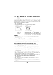
...pin conventional power connector (White) connect to use the SATA power cable & data cable, which are from our motherboard package. 5. Below operation procedure is available on our website: www.asrock.com 2. The latest SATA / SATAII driver is designed only for SATA / SATAII HDD in the product spec ...on our support website: www.asrock.com 4. 2.11 SA TA / SA TAII HDD Hot Plug F eature and Operation SAT SAT Feature Guide This motherboard supports Hot Plug feature for our motherboard, which cannot support Hot Plug function, will cause the HDD damage ...
...pin conventional power connector (White) connect to use the SATA power cable & data cable, which are from our motherboard package. 5. Below operation procedure is available on our website: www.asrock.com 2. The latest SATA / SATAII driver is designed only for SATA / SATAII HDD in the product spec ...on our support website: www.asrock.com 4. 2.11 SA TA / SA TAII HDD Hot Plug F eature and Operation SAT SAT Feature Guide This motherboard supports Hot Plug feature for our motherboard, which cannot support Hot Plug function, will cause the HDD damage ...
User Manual
Page 27
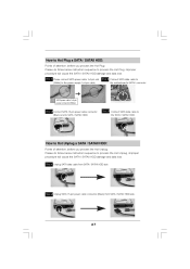
... loss. Step 2 Connect SATA data cable to the power supply 1x4-pin cable. Step 1 Please connect SATA power cable 1x4-pin end (White) to the motherboard's SATAII connector. Step 2 Unplug SATA 15-pin power cable connector (Black) from SATA / SATAII HDD side. Step 1 Unplug SATA data cable from SATA / SATAII HDD...
... loss. Step 2 Connect SATA data cable to the power supply 1x4-pin cable. Step 1 Please connect SATA power cable 1x4-pin end (White) to the motherboard's SATAII connector. Step 2 Unplug SATA 15-pin power cable connector (Black) from SATA / SATAII HDD side. Step 1 Unplug SATA data cable from SATA / SATAII HDD...
User Manual
Page 29
... fixed PCI / PCIE buses. Therefore, CPU FSB is untied during overclocking, FSB enjoys better margin due to [CPU, PCIE, Async.]. 2 . 1 5 Untied Overclocking T echnology Technology This motherboard supports Untied Overclocking Technology, which means during overclocking, but PCI / PCIE buses are in the fixed mode so that FSB can operate under a more stable...
... fixed PCI / PCIE buses. Therefore, CPU FSB is untied during overclocking, FSB enjoys better margin due to [CPU, PCIE, Async.]. 2 . 1 5 Untied Overclocking T echnology Technology This motherboard supports Untied Overclocking Technology, which means during overclocking, but PCI / PCIE buses are in the fixed mode so that FSB can operate under a more stable...
User Manual
Page 30
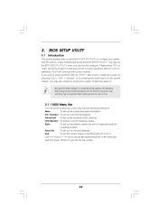
... with the following BIOS setup screens and descriptions are for reference purpose only, and they may also restart by pressing the reset button on the motherboard stores the BIOS SETUP UTILITY. Please press or during the Power-On-Self-Test (POST) to locate and load the Operating System Security To set...
... with the following BIOS setup screens and descriptions are for reference purpose only, and they may also restart by pressing the reset button on the motherboard stores the BIOS SETUP UTILITY. Please press or during the Power-On-Self-Test (POST) to locate and load the Operating System Security To set...


