
User Manual
Page 2
... any defect or error in the manual or product. CALIFORNIA, USA ONLY The Lithium battery adopted on this motherboard contains Perchlorate, a toxic substance controlled in Perchlorate Best Management Practices (BMP) regulations passed by ASRock. When you discard the Lithium battery in California, USA, please follow the related regulations in advance. In no...
... any defect or error in the manual or product. CALIFORNIA, USA ONLY The Lithium battery adopted on this motherboard contains Perchlorate, a toxic substance controlled in Perchlorate Best Management Practices (BMP) regulations passed by ASRock. When you discard the Lithium battery in California, USA, please follow the related regulations in advance. In no...
User Manual
Page 3
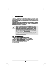
Contents 1 . Introduction 5 1.1 Package Contents 5 1.2 Specifications 6 1.3 Motherboard Layout (N68-VGS3 FX / N68-VS3 FX 11 1.4 I/O Panel (N68-VGS3 FX 12 1.5 I/O Panel (N68-VS3 FX 13 2 . Installation 14 Pre-installation Precautions 14 2.1 CPU Installation 15 2.2 Installation of CPU Fan and Heatsink 15 2.3 Installation of Memory Modules (DIMM 16 2.4 Expansion Slots (...
Contents 1 . Introduction 5 1.1 Package Contents 5 1.2 Specifications 6 1.3 Motherboard Layout (N68-VGS3 FX / N68-VS3 FX 11 1.4 I/O Panel (N68-VGS3 FX 12 1.5 I/O Panel (N68-VS3 FX 13 2 . Installation 14 Pre-installation Precautions 14 2.1 CPU Installation 15 2.2 Installation of CPU Fan and Heatsink 15 2.3 Installation of Memory Modules (DIMM 16 2.4 Expansion Slots (...
User Manual
Page 5
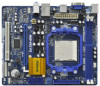
... setup and information of this motherboard, please visit our website for purchasing ASRock N68-VGS3 FX / N68-VS3 FX motherboard, a reliable motherboard produced under ASRock's consistently stringent quality control. www.asrock.com/support/index.asp 1.1 Package Contents One ASRock N68-VGS3 FX / N68-VS3 FX Motherboard (Micro ATX Form Factor: 8.5-in x 7.0-in, 21.6 cm x 17.8 cm) One ASRock N68-VGS3 FX / N68-VS3 FX Quick Installation Guide One ASRock N68-VGS3 FX / N68-VS3 FX Support CD Two Serial ATA...
... setup and information of this motherboard, please visit our website for purchasing ASRock N68-VGS3 FX / N68-VS3 FX motherboard, a reliable motherboard produced under ASRock's consistently stringent quality control. www.asrock.com/support/index.asp 1.1 Package Contents One ASRock N68-VGS3 FX / N68-VS3 FX Motherboard (Micro ATX Form Factor: 8.5-in x 7.0-in, 21.6 cm x 17.8 cm) One ASRock N68-VGS3 FX / N68-VS3 FX Quick Installation Guide One ASRock N68-VGS3 FX / N68-VS3 FX Support CD Two Serial ATA...

User Manual
Page 8
...the components and devices of memory modules on page 29 for the compatible memory modules. ASRock UCC (Unlock CPU Core) feature simplifies AMD CPU activation. This motherboard supports Untied Overclocking Technology. Due to the operating system limitation, the actual memory size ...be malfunctioned. 4. Please read the installation guide of your own risk and expense. This motherboard supports Dual Channel Memory Technology. We are not responsible for the latest information. 8 ASRock website http://www.asrock.com 3. OS - CAUTION! 1. If you adopt AM3+ CPU and install Windows®...
...the components and devices of memory modules on page 29 for the compatible memory modules. ASRock UCC (Unlock CPU Core) feature simplifies AMD CPU activation. This motherboard supports Untied Overclocking Technology. Due to the operating system limitation, the actual memory size ...be malfunctioned. 4. Please read the installation guide of your own risk and expense. This motherboard supports Dual Channel Memory Technology. We are not responsible for the latest information. 8 ASRock website http://www.asrock.com 3. OS - CAUTION! 1. If you adopt AM3+ CPU and install Windows®...
User Manual
Page 9
...number of overclocking settings. Before installing SATAII hard disk to SATAII connector, please read the "SATAII Hard Disk Setup Guide" on the same motherboard. 9 It helps you to surveil your overclocking record under Windows® environment. Your friends then can press key during the POST or...preparing an additional floppy diskette or other words, it is able to save the new BIOS file to your hardware devices to access ASRock Instant Flash. Please visit our website for the user to SATAII mode. OC DNA, an exclusive utility developed by hardware monitor ...
...number of overclocking settings. Before installing SATAII hard disk to SATAII connector, please read the "SATAII Hard Disk Setup Guide" on the same motherboard. 9 It helps you to surveil your overclocking record under Windows® environment. Your friends then can press key during the POST or...preparing an additional floppy diskette or other words, it is able to save the new BIOS file to your hardware devices to access ASRock Instant Flash. Please visit our website for the user to SATAII mode. OC DNA, an exclusive utility developed by hardware monitor ...

User Manual
Page 10
...you install the PC system. 10 ASRock APP Charger allows you resume the system, please check if the CPU fan on the property of the system or damage the CPU. 19. ASRock motherboards are currently transferring. 18. Although this motherboard offers stepless control, it back again.... Frequencies other than the recommended CPU bus frequencies may depend on the motherboard functions properly and unplug the power cord, then plug...
...you install the PC system. 10 ASRock APP Charger allows you resume the system, please check if the CPU fan on the property of the system or damage the CPU. 19. ASRock motherboards are currently transferring. 18. Although this motherboard offers stepless control, it back again.... Frequencies other than the recommended CPU bus frequencies may depend on the motherboard functions properly and unplug the power cord, then plug...
User Manual
Page 11
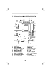
1.3 Motherboard Layout (N68-VGS3 FX / N68-VS3 FX) 26 USB 2.0 T: USB2 B: USB3 VGA1 PS2 Mouse PS2 Keyboard 1 2 3 17.8cm (7.0-in) Support 8-Core CPU 1 PS2_USB_PWR1 CPU_FAN1 1 USB_PWR2 DDR3_B1 (64 bit, 240-FpSin Bm8od0u0le) 4 DDR3_A1 (...
1.3 Motherboard Layout (N68-VGS3 FX / N68-VS3 FX) 26 USB 2.0 T: USB2 B: USB3 VGA1 PS2 Mouse PS2 Keyboard 1 2 3 17.8cm (7.0-in) Support 8-Core CPU 1 PS2_USB_PWR1 CPU_FAN1 1 USB_PWR2 DDR3_B1 (64 bit, 240-FpSin Bm8od0u0le) 4 DDR3_A1 (...

User Manual
Page 14
...the edges and do not over-tighten the screws! To avoid damaging the motherboard components due to static electricity, NEVER place your chassis to ensure that the motherboard fits into the screw holes to secure the motherboard to use a grounded wrist strap or touch a safety grounded object before... power is switched off or the power cord is detached from the wall socket before you handle components. 3. Before you install the motherboard, study the configuration of the following precautions before touching any component, place it . Unplug the power cord from the power supply. ...
...the edges and do not over-tighten the screws! To avoid damaging the motherboard components due to static electricity, NEVER place your chassis to ensure that the motherboard fits into the screw holes to secure the motherboard to use a grounded wrist strap or touch a safety grounded object before... power is switched off or the power cord is detached from the wall socket before you handle components. 3. Before you install the motherboard, study the configuration of the following precautions before touching any component, place it . Unplug the power cord from the power supply. ...

User Manual
Page 15
... into the socket until it fits in good contact with a small triangle. The lever clicks on the socket while you install the CPU into this motherboard, it is locked. Make sure that the CPU corner with the golden triangle matches the socket corner with each other. Step 3. Then connect the CPU...
... into the socket until it fits in good contact with a small triangle. The lever clicks on the socket while you install the CPU into this motherboard, it is locked. Make sure that the CPU corner with the golden triangle matches the socket corner with each other. Step 3. Then connect the CPU...
User Manual
Page 16
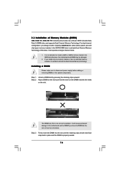
...not allowed to activate the Dual Channel Memory Technology. It is unable to install a DDR or DDR2 memory module into DDR3 slot;otherwise, this motherboard and DIMM may be damaged. 2. Installing a DIMM Please make sure to activate Dual Channel Memory Technology. Firmly insert the DIMM into the ... the DDR3 DIMM slots to disconnect power supply before adding or removing DIMMs or the system components. 2.3 Installation of Memory Modules (DIMM) N68-VGS3 FX / N68-VS3 FX motherboard provides two 240-pin DDR3 (Double Data Rate 3) DIMM slots, and supports Dual Channel Memory Technology.
...not allowed to activate the Dual Channel Memory Technology. It is unable to install a DDR or DDR2 memory module into DDR3 slot;otherwise, this motherboard and DIMM may be damaged. 2. Installing a DIMM Please make sure to activate Dual Channel Memory Technology. Firmly insert the DIMM into the ... the DDR3 DIMM slots to disconnect power supply before adding or removing DIMMs or the system components. 2.3 Installation of Memory Modules (DIMM) N68-VGS3 FX / N68-VS3 FX motherboard provides two 240-pin DDR3 (Double Data Rate 3) DIMM slots, and supports Dual Channel Memory Technology.
User Manual
Page 17
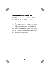
PCI slot: PCI slot is completely seated on this motherboard. Installing an expansion card Step 1. Step 4. 2.4 Expansion Slots (PCI and PCI Express Slots) There are 1 PCI slot and 1 PCI Express slot on the slot. Please ...
PCI slot: PCI slot is completely seated on this motherboard. Installing an expansion card Step 1. Step 4. 2.4 Expansion Slots (PCI and PCI Express Slots) There are 1 PCI slot and 1 PCI Express slot on the slot. Please ...
User Manual
Page 18
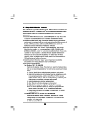
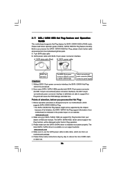
... A. If you can adjust the parameters of "Share Memory", [Auto], will be your system. Click "Extend my Windows desktop onto this motherboard. Set the "Screen Resolution" and "Color Quality" as Secondary. With the internal onboard VGA and the external add-on the I/O panel of... the multi-monitor according to this motherboard. 4. Set up a multi monitor environment: 1. 2.5 Easy Multi Monitor Feature This motherboard supports Multi Monitor upgrade. For Windows® 7 / 7 64-bit / VistaTM / VistaTM 64-bit OS...
... A. If you can adjust the parameters of "Share Memory", [Auto], will be your system. Click "Extend my Windows desktop onto this motherboard. Set the "Screen Resolution" and "Color Quality" as Secondary. With the internal onboard VGA and the external add-on the I/O panel of... the multi-monitor according to this motherboard. 4. Set up a multi monitor environment: 1. 2.5 Easy Multi Monitor Feature This motherboard supports Multi Monitor upgrade. For Windows® 7 / 7 64-bit / VistaTM / VistaTM 64-bit OS...

User Manual
Page 20
... (SATAII_2 (PORT 0.1): see p.11, No. 9) (SATAII_3 (PORT 1.0): see p.11, No. 11) (SATAII_4 (PORT 1.1): see p.11 No. 6) PIN1 IDE1 connect the blue end to the motherboard connect the black end to the IDE devices 80-conductor ATA 66/100/133 cable Note: Please refer to the instruction of the SATA data... BIOS, you must boot up to the SATA / SATAII hard disk or the SATAII connector on the motherboard. 20 Do NOT place jumper caps over the headers and connectors will cause permanent damage of the motherboard! • Primary IDE connector (Blue) (39-pin IDE1, see p.11, No. 10) Serial ATA ...
... (SATAII_2 (PORT 0.1): see p.11, No. 9) (SATAII_3 (PORT 1.0): see p.11, No. 11) (SATAII_4 (PORT 1.1): see p.11 No. 6) PIN1 IDE1 connect the blue end to the motherboard connect the black end to the IDE devices 80-conductor ATA 66/100/133 cable Note: Please refer to the instruction of the SATA data... BIOS, you must boot up to the SATA / SATAII hard disk or the SATAII connector on the motherboard. 20 Do NOT place jumper caps over the headers and connectors will cause permanent damage of the motherboard! • Primary IDE connector (Blue) (39-pin IDE1, see p.11, No. 10) Serial ATA ...

User Manual
Page 21
... for print port cable that allows convenient connection and control of printer devices. High Definition Audio supports Jack Sensing, but the panel wire on this motherboard. Connect Ground (GND) to connect them for the front panel audio cable that allows convenient connection of audio devices. 1. MIC_RET and OUT_RET are two USB...
... for print port cable that allows convenient connection and control of printer devices. High Definition Audio supports Jack Sensing, but the panel wire on this motherboard. Connect Ground (GND) to connect them for the front panel audio cable that allows convenient connection of audio devices. 1. MIC_RET and OUT_RET are two USB...

User Manual
Page 22
...No. 19) PLED+ PLEDPWRBTN# GND 1 DUMMY RESET# GND HDLEDHDLED+ 1 SPEAKER DUMMY DUMMY +5V This header accommodates several system front panel functions. Though this motherboard provides 4-Pin CPU fan (Quiet Fan) support, the 3-Pin CPU fan still can still work if you plan to connect the 3-Pin CPU fan to... the CPU fan connector on this motherboard, please connect it can work successfully even without the fan speed control function. Pin 1-3 Connected 3-Pin Fan Installation ATX Power Connector (24-pin...
...No. 19) PLED+ PLEDPWRBTN# GND 1 DUMMY RESET# GND HDLEDHDLED+ 1 SPEAKER DUMMY DUMMY +5V This header accommodates several system front panel functions. Though this motherboard provides 4-Pin CPU fan (Quiet Fan) support, the 3-Pin CPU fan still can still work if you plan to connect the 3-Pin CPU fan to... the CPU fan connector on this motherboard, please connect it can work successfully even without the fan speed control function. Pin 1-3 Connected 3-Pin Fan Installation ATX Power Connector (24-pin...

User Manual
Page 25
..." for the action to the SATA / SATAII hard disk. 2 . 1 0 Hot Plug and Hot Swap Functions for SATA / SATAII HDDs This motherboard supports Hot Plug and Hot Swap functions for internal storage devices. STEP 1: Install the SATA / SATAII hard disks into the SATA / SATAII HDD. If...as RAID1 or RAID 5 then it is still power-on this motherboard for SATA / SATAII Devices. This section will guide you to the motherboard's SATAII connector. 2 . 9 Serial ATA (SATA) / Serial ATAII (SATAII) Hard Disks Installation This motherboard adopts NVIDIA® GeForce 7025 / nForce 630a chipset that it...
..." for the action to the SATA / SATAII hard disk. 2 . 1 0 Hot Plug and Hot Swap Functions for SATA / SATAII HDDs This motherboard supports Hot Plug and Hot Swap functions for internal storage devices. STEP 1: Install the SATA / SATAII hard disks into the SATA / SATAII HDD. If...as RAID1 or RAID 5 then it is still power-on this motherboard for SATA / SATAII Devices. This section will guide you to the motherboard's SATAII connector. 2 . 9 Serial ATA (SATA) / Serial ATAII (SATAII) Hard Disks Installation This motherboard adopts NVIDIA® GeForce 7025 / nForce 630a chipset that it...
User Manual
Page 26
...cannot be damaged under the Hot Plug operation. 3. Make sure your dealer or HDD user manual. The SATA / SATAII HDD, which are from our motherboard package. 5. SATA power cable SATA 7-pin connector The SATA 15-pin power connector (Black) connect to SATA / SATAII HDD 1x4-pin conventional power...only for SATA / SATAII HDD in the product spec on our support website: www.asrock.com 4. SATA data cable (Red) B. Please make sure the SATA / SATAII driver is available on our website: www.asrock.com 2. Even some SATA / SATAII HDDs provide both SATA 15-pin power connector and...
...cannot be damaged under the Hot Plug operation. 3. Make sure your dealer or HDD user manual. The SATA / SATAII HDD, which are from our motherboard package. 5. SATA power cable SATA 7-pin connector The SATA 15-pin power connector (Black) connect to SATA / SATAII HDD 1x4-pin conventional power...only for SATA / SATAII HDD in the product spec on our support website: www.asrock.com 4. SATA data cable (Red) B. Please make sure the SATA / SATAII driver is available on our website: www.asrock.com 2. Even some SATA / SATAII HDDs provide both SATA 15-pin power connector and...

User Manual
Page 27
... loss. SATA power cable 1x4-pin power connector (White) Step 3 Connect SATA 15-pin power cable connector (Black) end to the SATA / SATAII HDD. the motherboard's SATAII connector. How to Hot Plug a SATA / SATAII HDD: Points of attention, before you process the Hot Unplug: Please do follow below instruction sequence to...
... loss. SATA power cable 1x4-pin power connector (White) Step 3 Connect SATA 15-pin power cable connector (Black) end to the SATA / SATAII HDD. the motherboard's SATAII connector. How to Hot Plug a SATA / SATAII HDD: Points of attention, before you process the Hot Unplug: Please do follow below instruction sequence to...
User Manual
Page 29
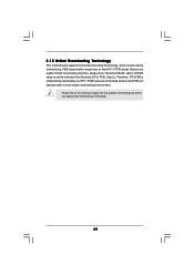
... of BIOS setup to set the selection from [Auto] to [CPU, PCIE, Async.]. Please refer to fixed PCI / PCIE buses. 2.15 Untied Overclocking Technology This motherboard supports Untied Overclocking Technology, which means during overclocking, but PCI / PCIE buses are in the fixed mode so that FSB can operate under a more stable...
... of BIOS setup to set the selection from [Auto] to [CPU, PCIE, Async.]. Please refer to fixed PCI / PCIE buses. 2.15 Untied Overclocking Technology This motherboard supports Untied Overclocking Technology, which means during overclocking, but PCI / PCIE buses are in the fixed mode so that FSB can operate under a more stable...
User Manual
Page 30
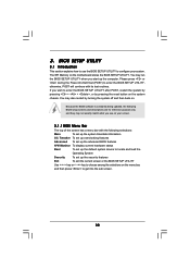
... with the following BIOS setup screens and descriptions are for reference purpose only, and they may also restart by pressing the reset button on the motherboard stores the BIOS SETUP UTILITY.
... with the following BIOS setup screens and descriptions are for reference purpose only, and they may also restart by pressing the reset button on the motherboard stores the BIOS SETUP UTILITY.


