User Manual
Page 18
...choose "Properties", and select the "Settings" tab so that the value you can adjust the parameters of the system memory. A. B. Select the display icon identified by the number one monitor will always be your system. G. Click the number "2" icon. 18 Enter "Share Memory" option to ... Repeat steps C through E for the second monitor. Install the NVIDIA® PCI Express VGA card to apply these new values. Press or to display a large number on PCI Express VGA card. 3. Set up a multi monitor environment: 1. Click the "Identify" button to enter BIOS setup. When...
...choose "Properties", and select the "Settings" tab so that the value you can adjust the parameters of the system memory. A. B. Select the display icon identified by the number one monitor will always be your system. G. Click the number "2" icon. 18 Enter "Share Memory" option to ... Repeat steps C through E for the second monitor. Install the NVIDIA® PCI Express VGA card to apply these new values. Press or to display a large number on PCI Express VGA card. 3. Set up a multi monitor environment: 1. Click the "Identify" button to enter BIOS setup. When...

User Manual
Page 19
... is "Open". Jumper Setting PS2_USB_PWR1 (see p.11, No. 1) 1_2 +5V 2_3 +5VSB Short pin2, pin3 to enable +5VSB (standby) for the display icon identified by the number one monitor to enable (see p.11, No. 15) 1_2 2_3 Default Clear CMOS Note: CLRCMOS1 allows you move items from... cap is my main monitor" and "Extend the desktop onto this monitor". The data in CMOS. B. Click and drag the display icons to positions representing the physical setup of display icons determines how you to short pin2 and pin3 on these 2 pins. Clear CMOS Jumper (CLRCMOS1) (see p.11, No....
... is "Open". Jumper Setting PS2_USB_PWR1 (see p.11, No. 1) 1_2 +5V 2_3 +5VSB Short pin2, pin3 to enable +5VSB (standby) for the display icon identified by the number one monitor to enable (see p.11, No. 15) 1_2 2_3 Default Clear CMOS Note: CLRCMOS1 allows you move items from... cap is my main monitor" and "Extend the desktop onto this monitor". The data in CMOS. B. Click and drag the display icons to positions representing the physical setup of display icons determines how you to short pin2 and pin3 on these 2 pins. Clear CMOS Jumper (CLRCMOS1) (see p.11, No....
User Manual
Page 30
... To set up the system time/date information OC Tweaker To set up overclocking features Advanced To set up the advanced BIOS features H/W Monitor To display current hardware status Boot To set up the default system device to enter the BIOS SETUP UTILITY, otherwise, POST will continue with the following BIOS...
... To set up the system time/date information OC Tweaker To set up overclocking features Advanced To set up the advanced BIOS features H/W Monitor To display current hardware status Boot To set up the default system device to enter the BIOS SETUP UTILITY, otherwise, POST will continue with the following BIOS...
User Manual
Page 31
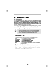
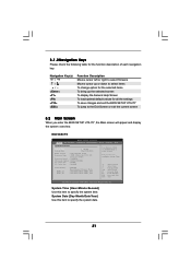
...the Exit Screen or exit the current screen 3.2 Main Screen When you enter the BIOS SETUP UTILITY, the Main screen will appear and display the system overview. N68-VGS3 FX BIOS SETUP UTILITY Main OC Tweaker Advanced H/W Monitor System Overview System Time System Date [17:00:09] [Tue 09/06/2011] ...BIOS Version : N68-VGS3 FX P1.00 Processor Type : AMD Athlon (tm) II X2 265 Processor (64bit) Processor Speed : 3300MHz Microcode Update : 100F63/10000B6 L1 Cache Size : 256KB...
...the Exit Screen or exit the current screen 3.2 Main Screen When you enter the BIOS SETUP UTILITY, the Main screen will appear and display the system overview. N68-VGS3 FX BIOS SETUP UTILITY Main OC Tweaker Advanced H/W Monitor System Overview System Time System Date [17:00:09] [Tue 09/06/2011] ...BIOS Version : N68-VGS3 FX P1.00 Processor Type : AMD Athlon (tm) II X2 265 Processor (64bit) Processor Speed : 3300MHz Microcode Update : 100F63/10000B6 L1 Cache Size : 256KB...

User Manual
Page 33
... Support. The configuration options depend on the CPU core you adopt. North Bridge Maximum Frequency It will display Processor Maximum Voltage for reference. ASRock UCC ASRock UCC (Unlock CPU Core) feature simplifies AMD CPU activation. AMD IO C-State Support This allows you ...to adjust CPU Active Core Control feature. Processor Maximum Voltage It will display North Bridge Maximum Frequency for reference. 33 Configuration options: [...
... Support. The configuration options depend on the CPU core you adopt. North Bridge Maximum Frequency It will display Processor Maximum Voltage for reference. ASRock UCC ASRock UCC (Unlock CPU Core) feature simplifies AMD CPU activation. AMD IO C-State Support This allows you ...to adjust CPU Active Core Control feature. Processor Maximum Voltage It will display North Bridge Maximum Frequency for reference. 33 Configuration options: [...

User Manual
Page 47
...] Select Screen Select Item Enter Go to enable or disable the Boot From Onboard LAN feature. Boot Up Num-Lock If this section, it will display the available devices on your system for you to configure the boot settings and the boot priority. HDS722580VL] [CD / DVD: 3S - CD - 3.6 Boot Screen In...
...] Select Screen Select Item Enter Go to enable or disable the Boot From Onboard LAN feature. Boot Up Num-Lock If this section, it will display the available devices on your system for you to configure the boot settings and the boot priority. HDS722580VL] [CD / DVD: 3S - CD - 3.6 Boot Screen In...
User Manual
Page 50
... further information. 50 or you need to contact ASRock or want to display the menus. 4.2.2 Drivers Menu The Drivers Menu shows the available devices drivers if the system detects the installed devices. Refer to visit ASRock's website at http://www.asrock.com; Please install the necessary drivers to activate... OS documentation for general reference only. Click on the file "ASSETUP.EXE" from the BIN folder in this chapter for more about ASRock, welcome to your CD-ROM drive. Because motherboard settings and hardware options vary, use the setup procedures in the Support CD to ...
... further information. 50 or you need to contact ASRock or want to display the menus. 4.2.2 Drivers Menu The Drivers Menu shows the available devices drivers if the system detects the installed devices. Refer to visit ASRock's website at http://www.asrock.com; Please install the necessary drivers to activate... OS documentation for general reference only. Click on the file "ASSETUP.EXE" from the BIN folder in this chapter for more about ASRock, welcome to your CD-ROM drive. Because motherboard settings and hardware options vary, use the setup procedures in the Support CD to ...
Quick Installation Guide
Page 15
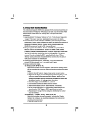
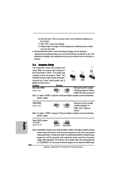
... Windows® 7 / 7 64-bit / VistaTM / VistaTM 64-bit OS: Right click the desktop, choose "Personalize", and select the "Display Settings" tab so that you have installed the onboard VGA driver already, there is less than the total capability of the multi-monitor according to... [32MB], [64MB], [128MB] or [256MB] to the VGA/D-Sub port on each monitor. A. Click the number "2" icon. 15 ASRock N68-VGS3 FX / N68-VS3 FX Motherboard English 2.5 Easy Multi Monitor Feature This motherboard supports Multi Monitor upgrade. Right-click the display icon and select "Attached", if necessary. G.
... Windows® 7 / 7 64-bit / VistaTM / VistaTM 64-bit OS: Right click the desktop, choose "Personalize", and select the "Display Settings" tab so that you have installed the onboard VGA driver already, there is less than the total capability of the multi-monitor according to... [32MB], [64MB], [128MB] or [256MB] to the VGA/D-Sub port on each monitor. A. Click the number "2" icon. 15 ASRock N68-VGS3 FX / N68-VS3 FX Motherboard English 2.5 Easy Multi Monitor Feature This motherboard supports Multi Monitor upgrade. Right-click the display icon and select "Attached", if necessary. G.
Quick Installation Guide
Page 16
... jumper is Short Open placed on CLRCMOS1 for 5 seconds. USB_PWR2 Short pin2, pin3 to enable (see p.2, No. 1) +5VSB (standby) for the display icon identified by power supply. Clear CMOS Jumper (CLRCMOS1) (see p.2, No. 3) +5VSB (standby) for 15 seconds, use . Use Multi Monitor ... and pin2 are setup. After waiting for USB4_5/6_7 wake up events. However, please do not clear the CMOS right 16 ASRock N68-VGS3 FX / N68-VS3 FX Motherboard English Jumper Setting PS2_USB_PWR1 Short pin2, pin3 to enable (see p.2, No. 15) Default Clear CMOS Note: CLRCMOS1 allows you...
... jumper is Short Open placed on CLRCMOS1 for 5 seconds. USB_PWR2 Short pin2, pin3 to enable (see p.2, No. 1) +5VSB (standby) for the display icon identified by power supply. Clear CMOS Jumper (CLRCMOS1) (see p.2, No. 3) +5VSB (standby) for 15 seconds, use . Use Multi Monitor ... and pin2 are setup. After waiting for USB4_5/6_7 wake up events. However, please do not clear the CMOS right 16 ASRock N68-VGS3 FX / N68-VS3 FX Motherboard English Jumper Setting PS2_USB_PWR1 Short pin2, pin3 to enable (see p.2, No. 15) Default Clear CMOS Note: CLRCMOS1 allows you...
Quick Installation Guide
Page 21
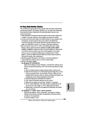
... untied during overclocking, FSB enjoys better margin due to fixed PCI / PCIE buses. For the detailed information about BIOS Setup, please refer to display the menus. 21 ASRock N68-VGS3 FX / N68-VS3 FX Motherboard English Software Support CD information This motherboard supports various Microsoft® Windows® operating systems: 7 / 7 64-bit / VistaTM / VistaTM 64-bit / XP...
... untied during overclocking, FSB enjoys better margin due to fixed PCI / PCIE buses. For the detailed information about BIOS Setup, please refer to display the menus. 21 ASRock N68-VGS3 FX / N68-VS3 FX Motherboard English Software Support CD information This motherboard supports various Microsoft® Windows® operating systems: 7 / 7 64-bit / VistaTM / VistaTM 64-bit / XP...

RAID Installation Guide
Page 16
Follow the Wizard for the two disk striped array that is displayed. Once that was created earlier. F. D. The 153.38 GB is for setting up and formatting the partition. Click on Administrative Tools. C. B. Double click on Disk Management. E. Double click on the Unallocated partition and select New Partition. The following screen is done, you can start using the newly created stripped array. 16 To create a partition on it, right click on Computer Management.
Follow the Wizard for the two disk striped array that is displayed. Once that was created earlier. F. D. The 153.38 GB is for setting up and formatting the partition. Click on Administrative Tools. C. B. Double click on Disk Management. E. Double click on the Unallocated partition and select New Partition. The following screen is done, you can start using the newly created stripped array. 16 To create a partition on it, right click on Computer Management.

RAID Installation Guide
Page 25
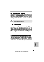
A. Double click on Computer Management. Double click on Administrative Tools. The following screen is displayed. 25 Click Next to confirm that the two-disk array has been created, it needs to use the default settings for RAID configurations. C. Click on Disk Management. D. Initializing NVRAID Array Disks Now that you agree to be partitioned and formatted. B. C. Click on Start → Settings → Control Panel. Click Finish to complete the steps of creating RAID array.
A. Double click on Computer Management. Double click on Administrative Tools. The following screen is displayed. 25 Click Next to confirm that the two-disk array has been created, it needs to use the default settings for RAID configurations. C. Click on Disk Management. D. Initializing NVRAID Array Disks Now that you agree to be partitioned and formatted. B. C. Click on Start → Settings → Control Panel. Click Finish to complete the steps of creating RAID array.


